Models 85622, 85628, 85626, 85637 Non-Metallic-REV1007 Page 20
Before servicing the check valves,
first shut off the suction line and then
the discharge line to the pump. Next,
shut off the compressed air supply,
bleed air pressure from the pump, and
disconnect the air supply line from
the pump. Drain any remaining fluid
from the pump. The pump can now be
removed for service.
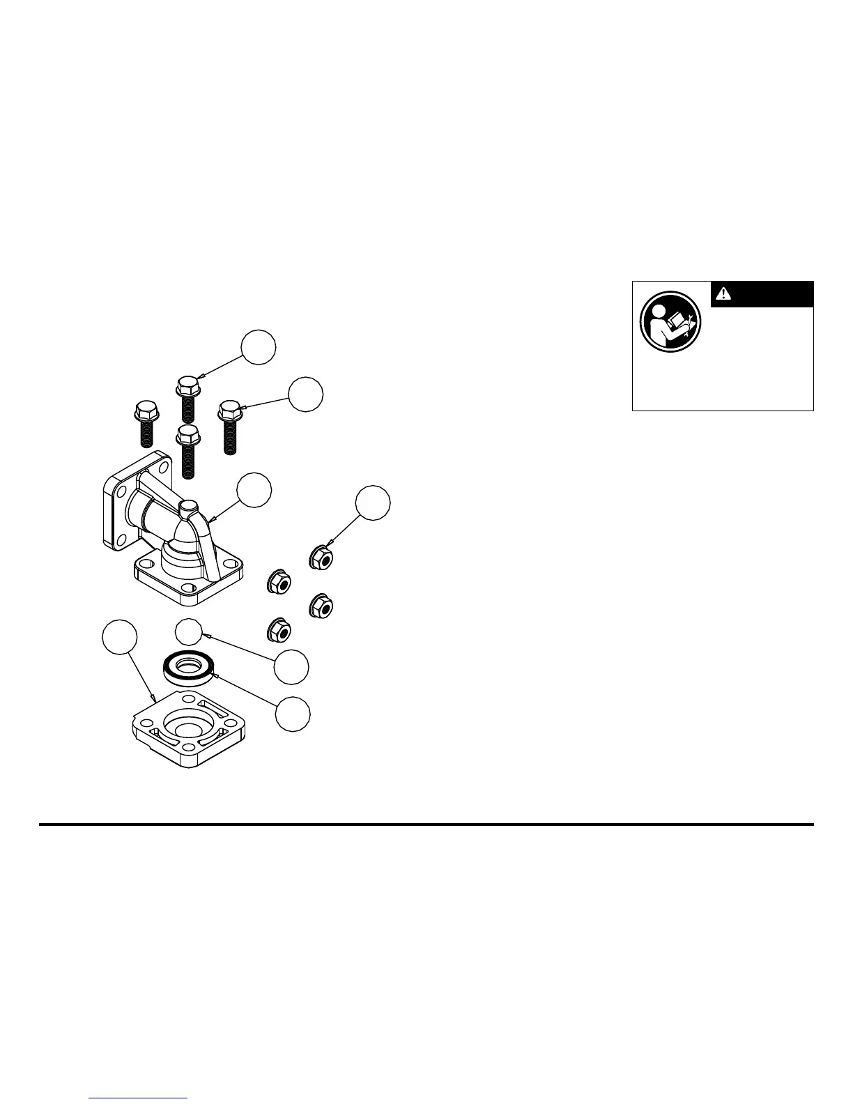
To access the modular check valve,
remove the elbows (items 17 and 18
from pump composite repair parts
drawing). Use a 1/2" wrench or socket to
remove the fasteners. Once the elbows
are removed, the modular check valves
can be seen in the cavities of the outer
chamber (items 14).
Inspect the check balls (items 2) for
wear, abrasion, or cuts on the spherical
surface. The check valve seats (items
34) should be inspected for cuts,
abrasive wear, or embedded material
on the surfaces of both the external
and internal chamfers. The spherical
surface of the check balls must seat
flush to the surface of the inner chamfer
on the check valve seats for the pump to
operate to peak efficiency. Replace any
worn or damaged parts as necessary.
Place a check ball (item 2) in the
ball cage of either the discharge elbow
or the outer chamber. Install a check
valve seat in the counter on each end
of the chamber. Refasten the elbows to
the chamber.



 To Next Page