Page Number - 3
Form 403693
FlowMaster™ Rotary Driven Electric Pump
Installing the Pump
Typical installation is shown only as a guide for selecting and
installing system components. Contact your Lincoln
Industrial representative for assistance in designing a
system to suit your specic needs.
The pump was tested in light weight oil which was left in to
protect the pump from corrosion. Flush the pump before con-
necting it to the system to prevent contamination of the grease
with residual oil.
1. Mount the pump securely on the drum cover so that it
cannot move or vibrate during operation.
2. Connect material supply line to the pump outlet. Install a
safety unloader [such as 272722 (4000 PSI, 276 bar) or
272572 (2500 PSI, 172 bar)] to outlet on opposite side of
the pump.
3. Install high pressure shut-off valve in the material supply
line. (Required)
Mount the pump securely on the drum cover. Failure to do
so could result in personal injury and equipment damage.
Always install a relief valve in the pump outlet to insure pump
pressure is below 5,000 PSI (2,500 PSI for Model 85569.
Use high pressure components to reduce risk of serious
injury including uid injection and splashing in the eyes or on
the skin.
is forced into the pump cylinder. Simultaneously, grease is discharged
through the outlet of the pump. The volume of grease during intake is
twice the amount of grease output during one cycle. During the upstroke,
the inlet check closes, and one half of the grease taken in during the pre-
vious stroke is transferred through the outlet check and discharged to the
outlet port. Typical output of the pump is shown on page 4.
Appropriate Use
• All pump models are exclusively designed to pump and
dispense lubricants using 24 VDC electric power.
• The maximum specication ratings should not be
exceeded.
• Any other use not in accordance with instructions will
result in loss of claims for warranty and liability.
Pump Performance and Specication
Operating Temperature, °F (°C)- -40 to +150 (-40 to 65)
Operating Voltage, VDC - 24 (18 MIN., 32 MAX)*
Motor, HP (kW) 1/2 (0.37)
Current draw, AMPS See tables 2, 3, 4, & 5
Output/pump cycle, in
3
(cm
3
) 0.07 (1.15)
Pump performance See table 1
Pump Outlets, In - 1/4” NPTF Female
Weight, Lbs (Kg) - 30 (13.3)
ELECTRIC PUMP PERFORMANCE SPECIFICATIONS
CUBIC IN/MIN Test conducted with Alvania NLGI#2 Grade Grease at 1000 psi Backpressure
TEMPERATURE DEG F (DEG C) 50 RPM 100 RPM 150RPM 200 RPM 250 RPM 300 RPM 350 RPM
80 (27) 3.5 7 10.5 14 17.5 21 24.5
40 (4) 3.5 7 10.5 14 17.5 21 24.5
20 (-7) 3 6 9 12 15 18 21
0 (-18) 3 6 9 12 15 18 21
-10 2.5 5 7.5 10 12.5 15 17.5
* Motor controller will shut motor off outside voltage limits.
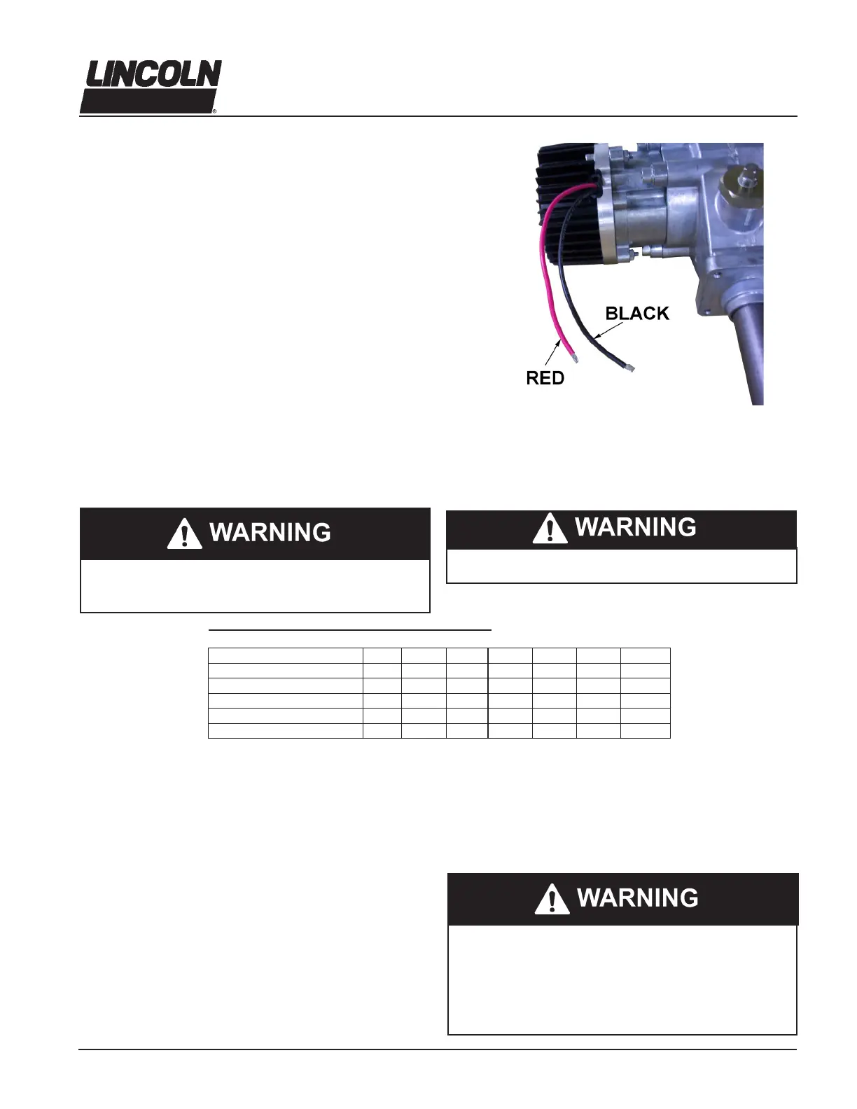
4. Wire the pump motor and vent valve (if used) as shown in
Illustration 1.
5. Connect power to motor leads. Be sure to connect red
motor lead to the positive side of the circuit (see Illustration
1A). The motor is polarity sensitive and will not run if im-
properly wired. Fuse the motor as recommended in Tables
2, 3, 4 & 5.
Table 1
ILLUSTRATION 1A
Pumps are not equipped with a high pressure shut-off valve.
Do not exceed maximum rated outlet pressure for these
pumps. Exceeding rated pressure may result in damage
to system components and personal injury.