Page Number - 5
Form 403693
FlowMaster™ Rotary Driven Electric Pump
* A eld installed fuse of 5 amps is recommended.
ELECTRIC FLOWMASTER PUMP
24 VDC, 34:1 Gear Ratio, 2 Stage 85552 & 85553
Back Pressure (PSI) RPM Current Draw (AMPS)*
0 58.2 1.16
1000 57.6 1.57
2000 57.0 2.10
3000 56.5 2.62
4000 55.9 3.20
5000 55.4 4.20
* A eld installed fuse of 20 amps is recommended.
Table 2
Table 3
ELECTRIC FLOWMASTER PUMP
24 VDC 19:1 Gear Ratio, 2 Stage, 85554 & 85566
Back Pressure (PSI) RPM Current Draw (AMPS)*
0 105 1.28
1000 103 2.03
2000 101 2.96
3000 99 3.68
4000 98 4.83
5000 96 6.47
ELECTRIC FLOWMASTER PUMP
24 VDC, 5:1 gear ratio, 85567, 85568, 85591
BACK PRESSURE (PSI) RPM CURRENT DRAW (AMPS)*
0 375 2
1000 350 4.5
2000 325 7.3
3000 300 9.6
4000 280 12
5000 250 15.3
* Fuse for 6 amps
* Fuse for 10 amps
Table 4
Table 5
ELECTRIC FLOWMASTER PUMP
24 VDC, 17.8:1, gear ratio, 2-stage 85569
BACK PRESSURE (PSI) RPM CURRENT DRAW (AMPS)*
0 107 1.28
1000 105 2
2000 103 2.75
2500 100 3.2
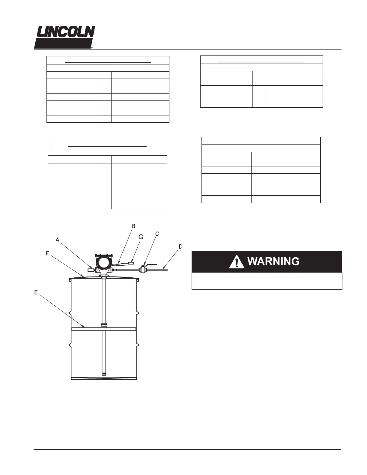
Illustration 2
A - Safety Unloader 272722 or 272572
B - 24 VDC from Controller
C- Outlet Shut-off Valve
D - Material Supply Line
E - Follower Plate (85492 for 120 lb.)
F - Drum Cover (84616 for 120 lbs.)
G - Field Installed Fuse
Operation
All pumps are set to run at full speed. Do not change the
settings for the pump until after the start up procedure.
1. Remove the pump outlet line.
2. With the pump in a full container of lubricant, energize the
pump. Make sure all air has been expelled from the pump
and even lubricant ow is achieved.
3. Reattach the pump outlet line. Never allow the pump to run
dry of lubricant. Monitor the supply lubricant level and rell
when necessary.