Service Training
Section 6
Page 16
Connector 1X5
Terminal Colour Function
1 PK Horn output positive
2 VT Initial lift output positive
3 WH Initial lowering output positive
4
5 WHRD Anti-crash switch output positive
6 GY Accelerator potentiometer supply negative
7 OG Link potentiometer (mid point)
8 YE Supply +10 V accelerator potentiometer
9 BU Forward / reverse movement switch output positive
10 RD Card supply input positive A1
11 BK Anti-crash switch input negative
12 BK(801) Output negative to tiller base microswitch
13 GN Tiller base input negative
14 WHBU Anti-crash signal output negative
15 GY(802) Input negative via tiller base
16 BN Tiller base signal output negative
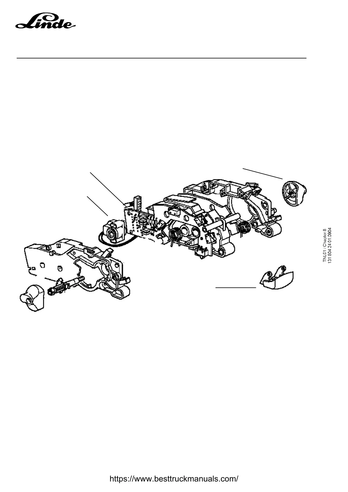
6.1.7 Control module tiller in version AP- Handlebar in version SP - A1
6.1.7.1 Description
The control unit is identical to the old range of trucks and is common to the two versions, AP and SP. Only
the traction potentiometer 1B1 can be and must be regulated while changing the control unit or a
replacement of the LAC. The potentiometer value must be regulated precisely and this precision can only
be obtained by using the PathFinder software.
The anti-crash safety microswitch 1S3 for the operator is located behind a red button that can be activated
in the AP version, and behind a black cover in the SP version forbidding the use of this safety (the driver
is protected by the outer hull of the truck).
Potentiometer
Anti-crash button
Throttle
Electronic circuit
https://www.besttruckmanuals.com/