05/30/08 Page 5 of 6
LINE 6 CONFIDENTIAL
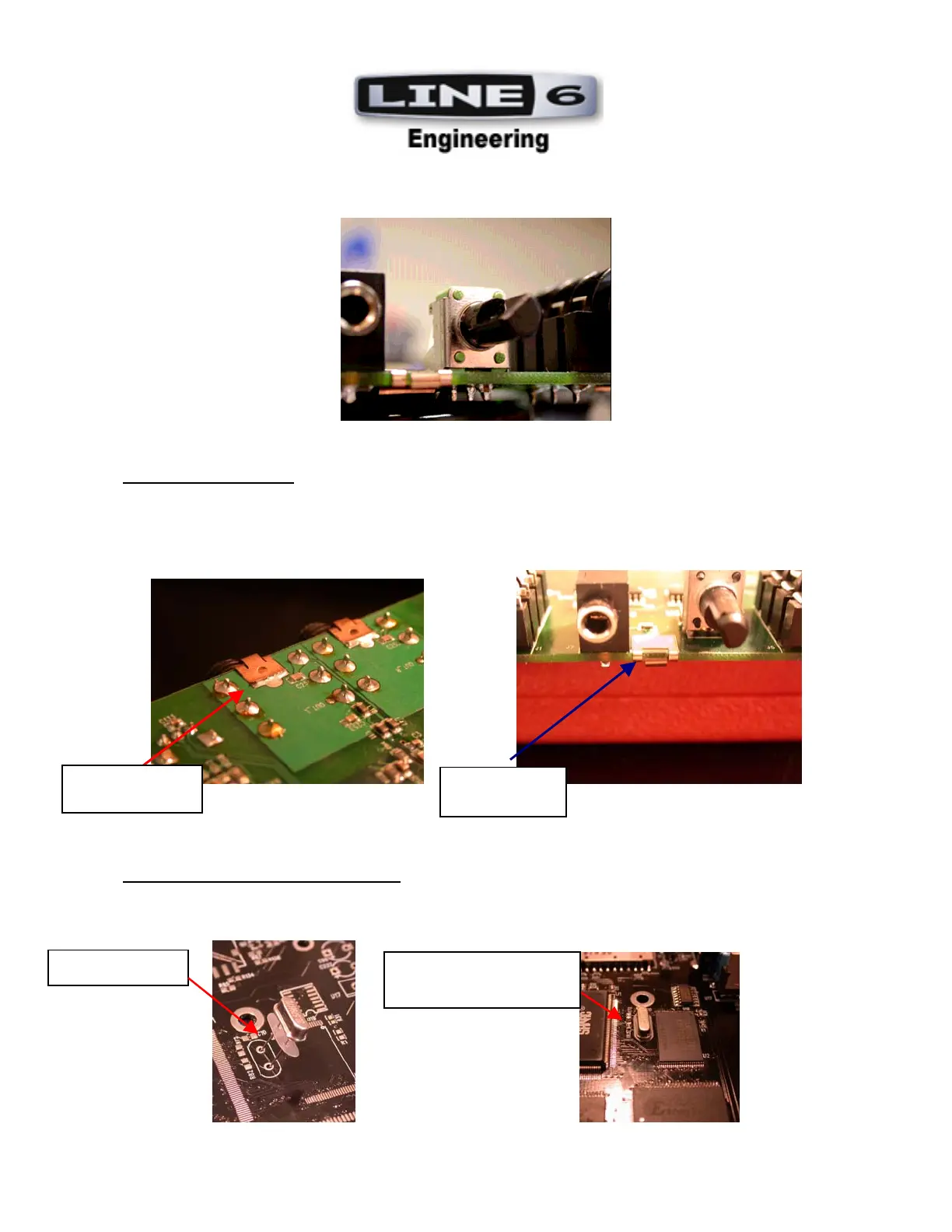
8. POTS: Be sure both horizontally mounted Pots (01-48-9208 and 01-48-9209) are installed flush to
the PCB and are aligned with the silkscreen outline within +/-1 degree of accuracy. See Photo.
9. GROUND FINGERS: ALL grounding fingers are mounted flush against the PCB edge. They are
mounted with their center clip hole on the BOTTOM side of the PCB. The “curl” of the grounding
finger should curve toward the TOP SIDE (toward the jack). They should then be manually
soldered on the BOTTOM SIDE.
See Photos:
BOTTOM SIDE TOP SIDE
10. CRYSTALS AND INSULATORS: Crystals Y1 (P/N 11-00-1002) and Y2 (11-00-1001) are to be
installed with insulator (30-15-0007) and must be mounted flush against PCB. See Photos:
INSULATOR
TAB CURLS
UPWARD
SOLDERED ON
BOTTOM SIDE
CRYSTAL INSTALLED
WITH INSULATOR
 Loading...