03/27/08 Page 4 of 7
LINE 6 CONFIDENTIAL
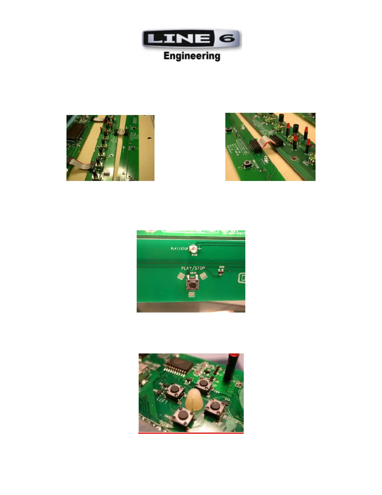
4. 10-Pin Ribbon Cable (21-30-0053-1) should be staked from J10 on User Interface Lower PCB (35-00-0272-
2) to J101 on UI Middle PCB (35-00-0272-1). See Photos.
5. SWITCHES: All tact switches are to be mounted flush and manually soldered on the bottom side of the User
Interface Lower PCB (35-00-0272-2) and UI User Interface Upper PCB (35-00-0272). See Photo
6. 4-WAY SWICH NYLON PIVOT: Install Nylon Pivot (PN 30-27-0221) into mounting hole on User
Interface Upper PCB (35-00-0272). See Photo
All tact switches are surface
mount and should be wave
soldered.
Switches should be flush with
the PCB and lined up with the
silkscreen outline within +/- 1
degree of accuracy.
 Loading...