3
6. TROUBLE SHOOTING GUIDE
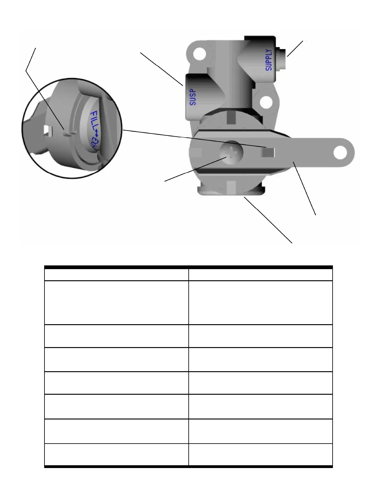
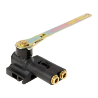
Figure 1. Installation Diagram
PROBLEM POSSIBLE CAUSE
Air springs flat
Obstruction in air line
Insufficient air pressure to suspension
Defective Pressure Protection Valve
Defective HCV-see test procedure
Air leak in system
Air Springs raise to full height but do not exhaust
Obstructed air line
Defective HCV-see test procedure
Air springs deflate when parked
Leak in air system-check with soapy water
Defective HCV-see test procedure
Suspension will not maintain proper height
Obstructed air line
Defective HCV-see test procedure
Hard ride
Ride height out of adjustment-readjust per vehicle
service manual
Valve works backward
Rotate notch in drive bearing 180° and reinstall
lever
Cab suspension overshoots center
Replace shocks
Use short delay H00450 HCV
EXHAUST PORT
LEVER
AIR SUPPLY
1/8” NPT OR
1/4” OD HOSE
PTC
TO AIR SPRINGS
1/8” NPT OR
1/4” OD HOSE
PTC
ALIGNMENT NOTCHES
LEVER SCREW
TORQUE TO
45-50 IN-LBS