LINK MANUFACTURING, LTD.
223 15TH ST. NE, SIOUX CENTER, IA 51250
1-800-222-6283 www.linkmfg.com
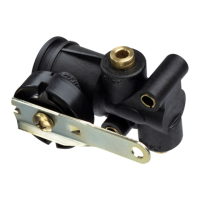
7. HCV TEST PROCEDURE
7.1
With a minimum of 90 psi at the supply port, rotate the
lever up (as indicated on the side of the valve) 30
o
to
45
o
. Air should begin to flow into the air springs.
7.2
Rotate the lever to the neutral position. Air flow should
stop.
7.3
Rotate the lever down 30
o
to 45
o
. Air should begin to
exhaust from the air springs.
7.4
Rotate the lever to the neutral position. Air flow should
stop.
7.5
If the valve fails to flow air or shut off as specified, re-
place with a new one.
8. REASONS TO REPLACE THE HCV
8.1
• HCV did not pass the test procedure
• Air leaks from the HCV
• HCV is damaged