960-3100-00 iPonic 614 Installation Manual 31
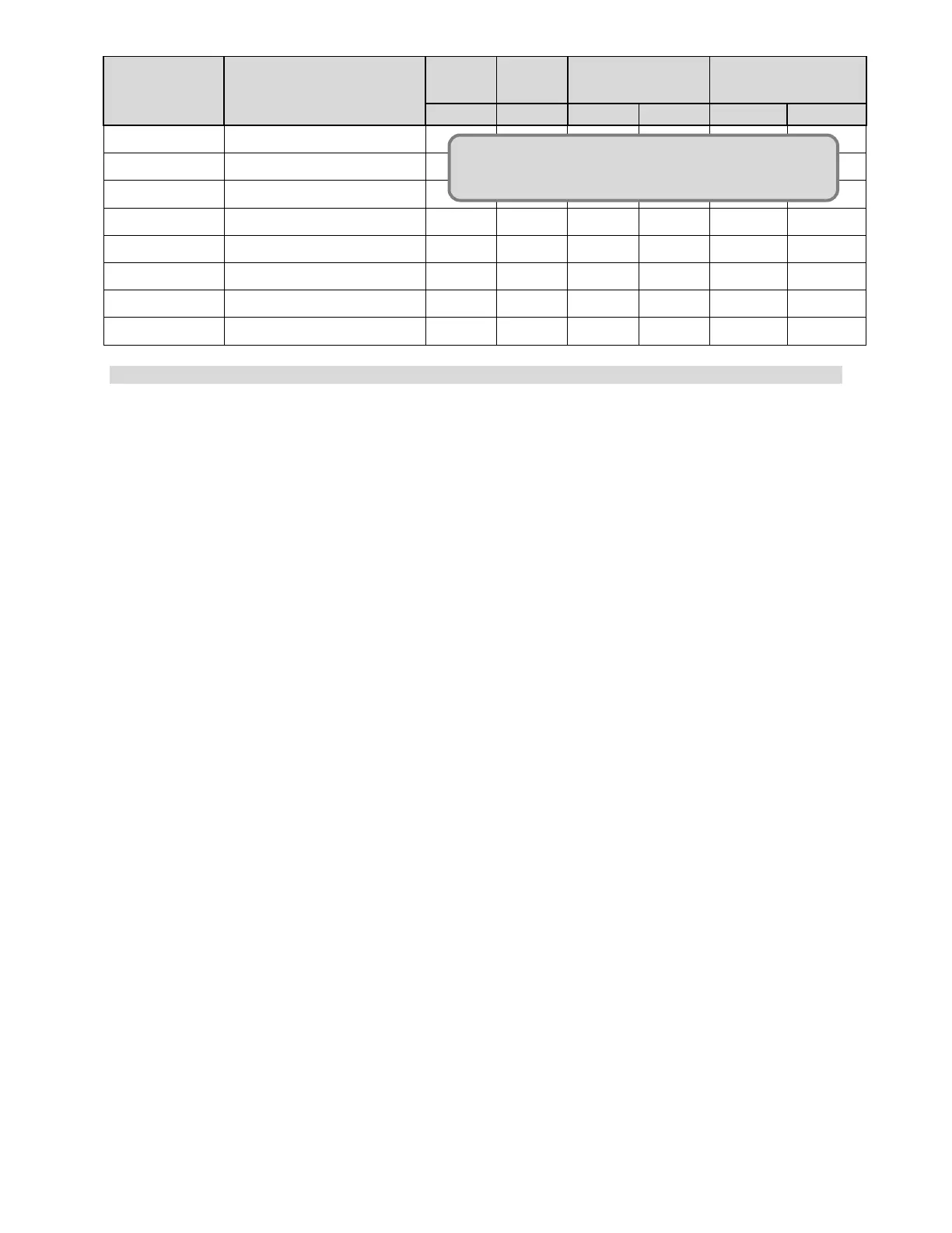
OUTPUT #
EQUIPMENT
NAME
COOL STAGES
❶ LIGHT
❷ CO2
❸ IRRI PUMP
❹ DEHUM
❺ HEATER
❻ VENT FANS
❼ UNIT FAN
❽ AC
Figure 2.4 Recommended Temperature Stages for AC/Heater Setup
Adding Additional Controlled Equipment of the Same Type
By default you can setup the controller to recognize one piece of equipment per type. An advanced
setting will allow you to choose any of the 8 outputs (including the unnamed relays) and change or set the
type of the equipment the controller will recognize as being installed at that output.
Menu->SystemSetup->EquipmentSetup->Advanced->Choose the Output for which you would like to
change the Name and Type->button 3 “Initial Settings”-> button 1 to select the equipment type of the
equipment you’ve installed, highlight the correct type and press OK. Button 3 will allow you to
name/rename the equipment to anything you like (such as “Light Bank 2”.)
Controlling Multiple Lighting Outputs
If you add an additional light bank, follow the instructions for Adding Additional Controlled Equipment of
the Same Type this will enable the Change Light Banks Mode (button 1) in your Light Settings screen.
Now whenever you change your light settings you have the option of using one bank or the other, both
concurrently or both alternately.
Adding an Alarm Output
An alarm output is not one of the basic equipment types but can easily be added to your controller. An
advanced setting will allow you to choose any of the 8 outputs (including the unnamed relays) and set the
type of the equipment the controller will recognize as being installed at that output as an alarm. After
installing the alarm you will be prompted to choose which alarms the alarm output should notify you of.
Menu->SystemSetup->EquipmentSetup->Advanced->Choose the Output for which you would like to change
the Name and Type->button 3 “Initial Settings”-> button 1 to select the equipment type of the equipment you’ve
installed, highlight “Alarm” and press OK. Button 3 will allow you to name/rename the equipment to anything you
like.
Wiring a Sensaphone to Dry Contacts
1. Make sure all power cables are unplugged before attempting to wire any equipment.
2. Open up the front panel to the 90 deg. position.
3. Find a location for the Sensaphone that is near the controller.
4. Run the free end of the cable to the controller unit.
5. You may extend the cable as needed, but make sure to use an adapter and wire approved by Link4 to
make any extensions (the wire and adapter can be purchased from Link4). If any splices are needed to
extend cable length, make certain they are WATERTIGHT. Water or fertilizer infiltration WILL cause
unstable sensor readings.
6. Carefully insert the cable through the bottom of the enclosure. It is easy to strip insulation and/or break
wires when pulling cable. Use UV protected “tie wraps” (typically blue or black), and do not over-tighten.