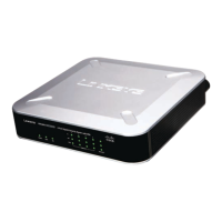
2224 Layer 2 Management 24-Port 10/100 Ethernet Switch
n
nect II 2224
3
ProConnect II
®
Series
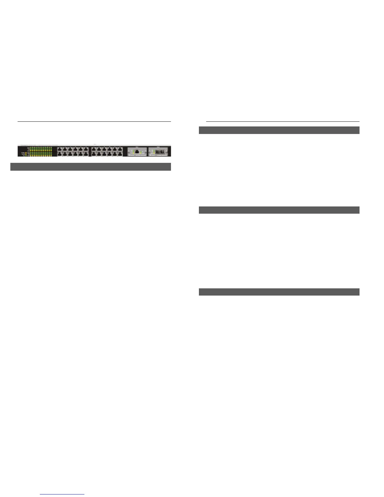
Getting to Know the Switch
Link/Act Green. Lights to indicate that the switch is successfully connect-
ing to the network. Blinks to indicate the switch is actively
receiving or sending the data over the port.
10/100 Green. Lights to indicate that the port is operating at 100 Mbps.
Off to indicate that he port is operating at 10 Mbps while the
switch is still working.
FDX/COL Amber. Lights to indicate that the port is operating in full-
duplex mode. Blinks to indicate that the connection is experi-
encing collisions.
Fan Red. Lights to indicate that the fans are not active.
TEMP Red. Lights to indicate that the switch exceeds its operational
temperature.
Power Green. Lights to indicate that the switch has power.
2
The Switch is equipped with twenty-four auto-sensing RJ-45 ports. These RJ-
45 ports support network speeds of either 10Mbps or 100Mbps, and can oper-
ate in half and full-duplex modes. Auto-sensing technology enables each port
to automatically detect the speed of the device connected to it (10Mbps or
100Mbps), and adjust its speed and duplex accordingly.
To connect a device to a port, you will need to use a network cable. You will
need to use Category 5 (or better) cable. For more information on twisted-
pair cabling, refer to the Twisted-Pair Cabling section.
The Switch is equipped with two expansion ports that provide for the installa-
tion of one or two expansion modules. These ports provide links to high-
speed network segments or individual workstations at speeds of up to
1000Mbps (Gigabit Ethernet).
To establish a Gigabit Ethernet connection, you will need to install an SX or
TX Gigabit expansion module and use Category 5e cabling or fiber optic
cabling. for more information on fiber optic cabling, refer to the Fiber Optic
Cabling section.
The Switch is equipped with a serial port labeled CONSOLE (located on the
front of the switch) that allows you to connect to a computer’s serial port (for
configuration purposes) using the provided serial cable.
The Gigabit Expansion Ports
The Console Port
The RJ-45 Ports
LEDs
 Loading...