3
lippert.com 432-LIPPERT (432-547-7378) CCD-0003928 Rev: 08.27.21
Sway Command
®
1.5
(AU) BY TRAILAIR
Installation and Owner’s Manual
(For Aftermarket Applications)
Installation
Mounting Controller
Never drill into the Sway Command controller or
compromise the pressure equalizer plug hole on the back
of the controller. Doing so voids the warranty and could
damage the controller.
NOTE: The Sway Command
controller is water-resistant,
but not waterproof. Do not spray high pressure water
directly at the controller.
Standard Chassis Mounting
1. The controller must be mounted in a level condition,
centered on the crossmember, and according to the
orientation arrow on the label (Fig.2A).
NOTE: The controller MUST be mounted facing the rear
of the caravan. The controller will not operate correctly if
mounted improperly.
2. Place the controller against the mounting surface. Use
a paint marker or grease pencil to locate the four mounting
holes for the Sway Command module (Fig.2B).
3. Using a drill with the 5.5 mm drill bit, drill
pilot holes through the crossmember at the four
previously marked locations. Clear all chips from the
mounting surface.
4. After the holes have been drilled, insert M6 x 11.0 x 0.7
serrated external lock washers over each #14 - 10 x 25 mm
self-drilling hex screw.
5. Insert assembled screws into the module as follows:
A. Insert one screw into the module and tighten half way
to hold the module in place.
B. Insert a second screw into the opposite corner from
the previously installed screw and tighten half way into the
module to hold the module in place.
C. Insert a third screw into the open hole on the opposite
end from the previously installed screw and tighten half
way into the module.
D. Insert the fourth screw into the remaining open hole
and tighten half way into the module.
6. Using an impact driver, securely fasten all screws using
a crisscross pattern (Fig.2) until screw heads are nearly
Fig.1
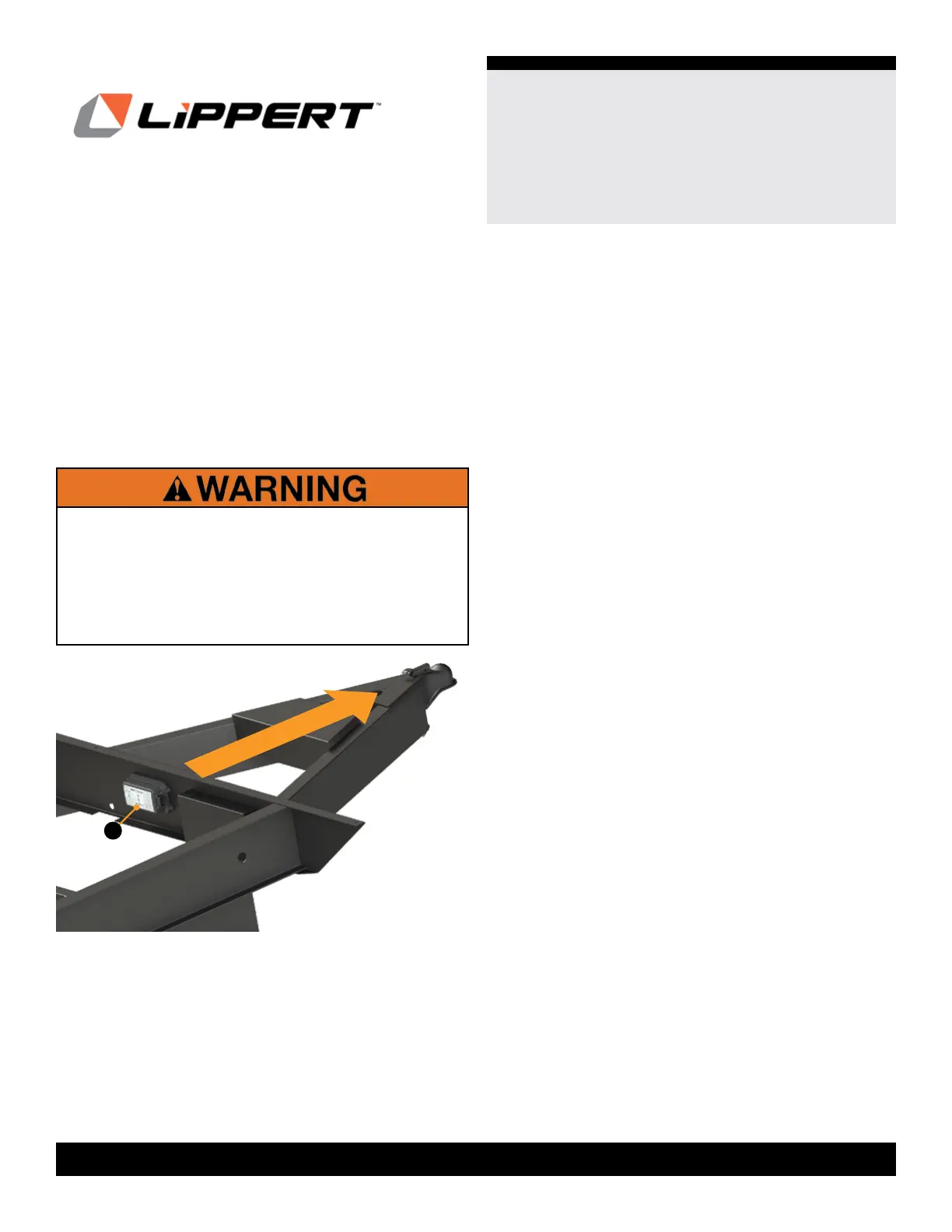
NOTE: The provided Sway Command controller module
(Fig.1A)
chassis, at the front of the chassis frame.
NOTE: The controller must be mounted to a frame
crossmember between 1219 mm - 3048 mm (4 ft - 10 ft)
behind the hitch point.
DIRECTION OF TRAVEL
A
IF THE CONTROLLER IS FITTED TO A CHASSIS
SHORTER THAN 101.6 MM (4”) IN HEIGHT, A
PROTECTIVE BRACKET/SHIELD MUST BE FITTED TO
PROTECT THE CONTROLLER FROM DAMAGE THAT
MAY BE CAUSED BY EXCESS WATER SPRAY AND
ROAD DEBRIS. SEE SHORT CHASSIS MOUNTING
INSTRUCTIONS AND FIGURE 3.