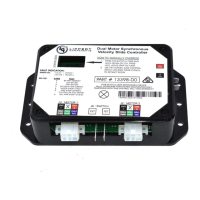
*********Do not push shaft up further than 1 ½ inches.************
b. The coupler will be lifted above the motor mount and can be removed with a pair of needle nose
pliers or hemostats.
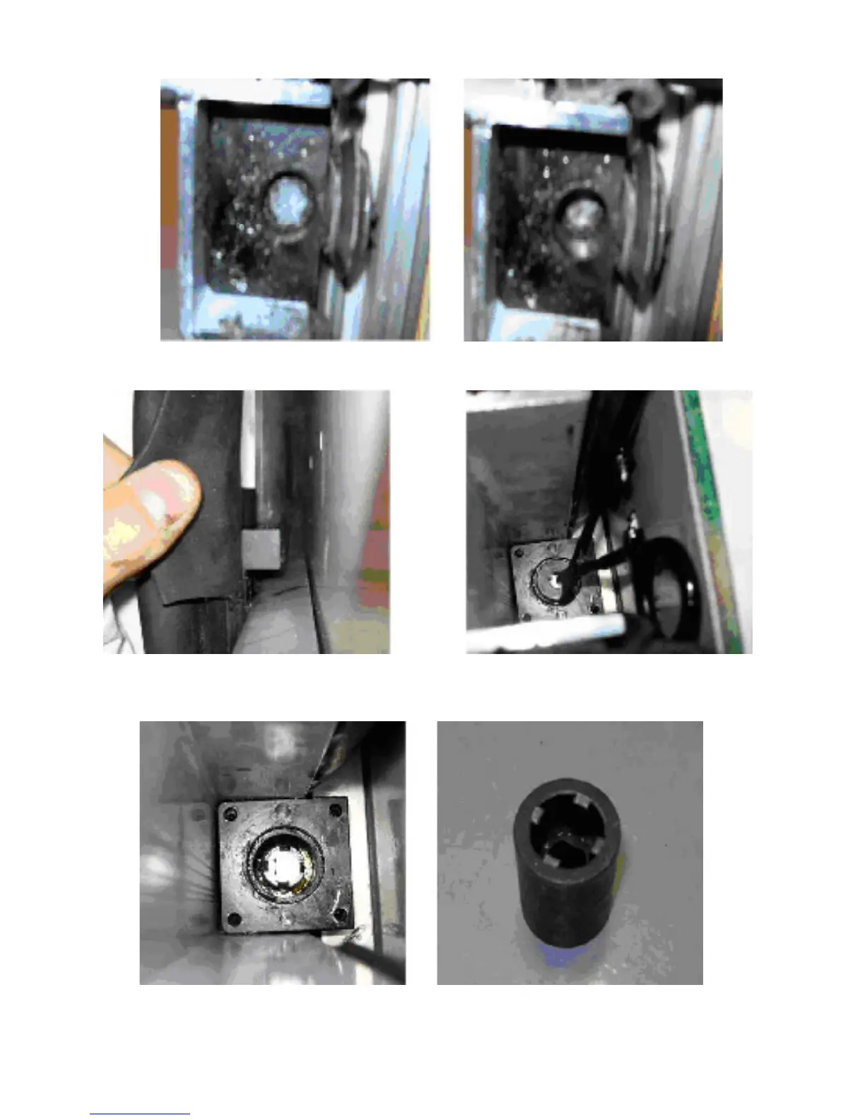
7. The coupler needs to be placed onto the end of the drive shaft, inside the motor mount, at the
top end of the column. Note the splines on the drive shaft and motor coupler.
11
The coupler can be rotated while pushing down, or the side column can be pushed back and forth
while pushing down, to engage the splines. The coupler should be pushed down below the top of the
motor mount.