12
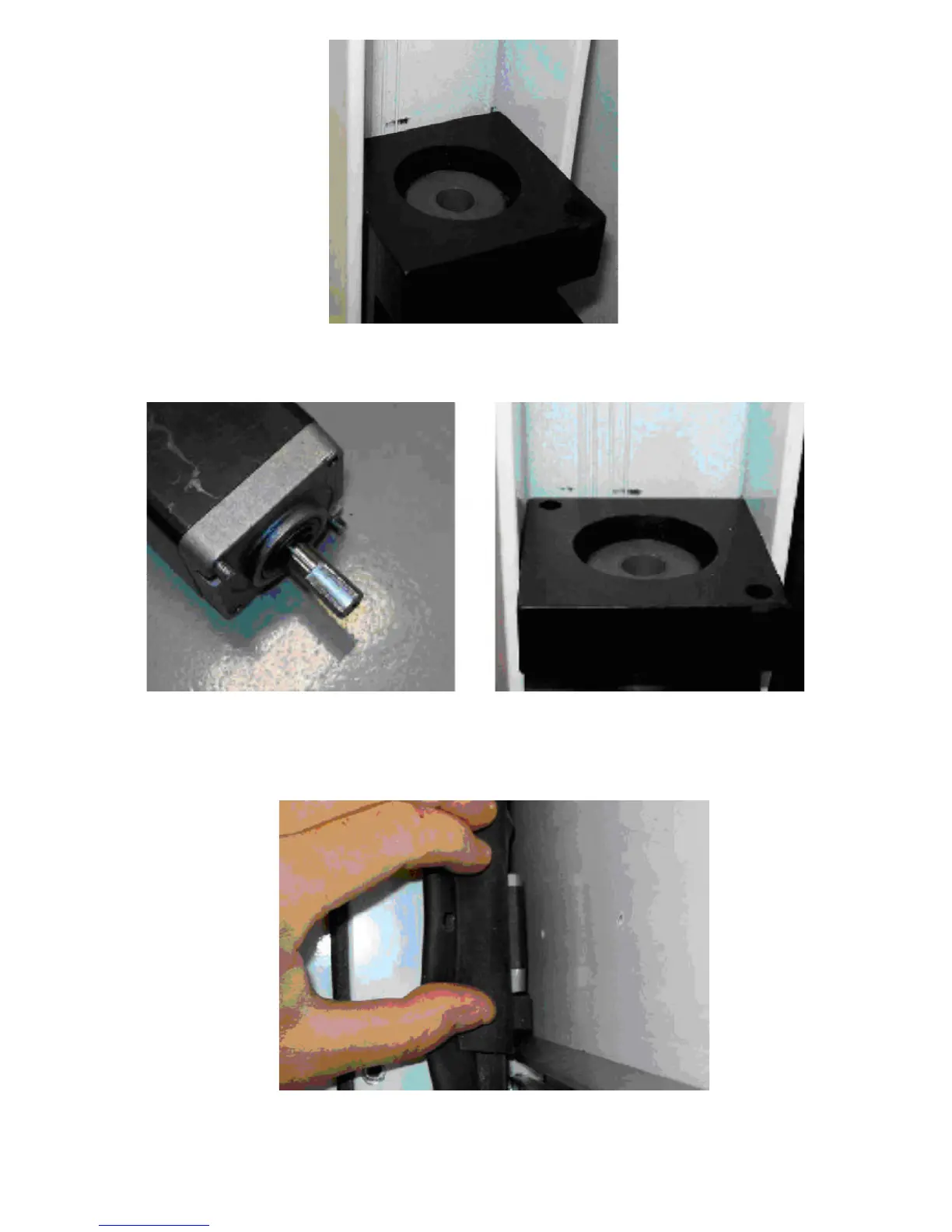
8. The motor can now be installed. Insert the motor through the top of the side column. Note the
screws protruding from the shaft end of the motor. They enter into the 2 holes in the corners of
the motor mount. Pay attention to the orientation of the screws and mating holes.
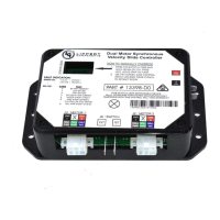
9. Align the motor shaft with the hole in the coupler, the motor should drop part of the way into the
coupler. While pushing down on the motor, slide the side column back and forth on the racks to
rotatethecouplerandalignthecoupleratwiththeatonthemotorshaft.Whentheatslineup,
the motor will drop down onto the motor mount.
10. Replace the motor retention screw.