EasyManuals Logo

Lippert Components OneControl HVAC Control 2.0 User Manual

Lippert Components OneControl HVAC Control 2.0
10 pages
To Next Page IconTo Next Page
To Previous Page IconTo Previous Page
Page #8 background imageLoading...
Page #8 background image
Rev: 02.05.21 Page 8 CCD-0001448
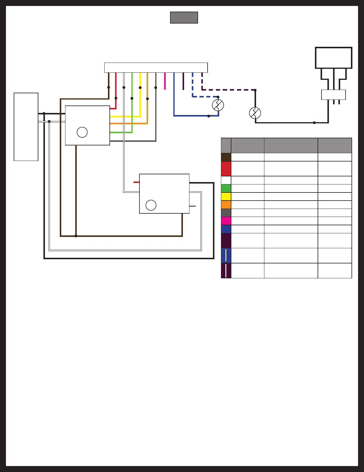
OneControl® HVAC Zone Wiring Diagram
Furnace, AC, Heatpump, Dual-speed Fan
Generator
(optional)
1 2 3
4 5 6
Zone Connector (406350 Controller)
1 7 2 8 3 9 4 10 5 11 6 12
T
T
THERM
T
T
THERM
Breaker Box
AC Hot
AC Neut
AC Hot
AC Neut
Gnd
Gnd
12V to Zone
12V to Zone
Compressor
Rev. Valve
High Fan
Low Fan
Heat Demand
LP Gas Supply
Zone T Sense
Outdoor T Sense (optional)
Color Signal
Zone
Connect
Brown Gnd 1
Red
Zone Power
(+12V DC)
7
White Gas Heat 2
Green High Fan 8
Yellow Compressor 3
Orange Rev. Valve 9
Gray Low Fan 4
Pink Reserved 10
Blue Zone Temp Input 5
Purple
Freeze Detect
Input
11
Blue w/
stripe
Sensor Power 6
Purple
w/stripe
Sensor Power 12
Fig. 10

Other manuals for Lippert Components OneControl HVAC Control 2.0

Questions and Answers:

Question and Answer IconNeed help?

Do you have a question about the Lippert Components OneControl HVAC Control 2.0 and is the answer not in the manual?

Lippert Components OneControl HVAC Control 2.0 Specifications

General IconGeneral
BrandLippert Components
ModelOneControl HVAC Control 2.0
CategoryController
LanguageEnglish

Related product manuals