Rev: 02.05.21 Page 7 CCD-0001448
Wiring Diagram
The following diagrams show the possible appliance connections depending on the OEM installed
controller.
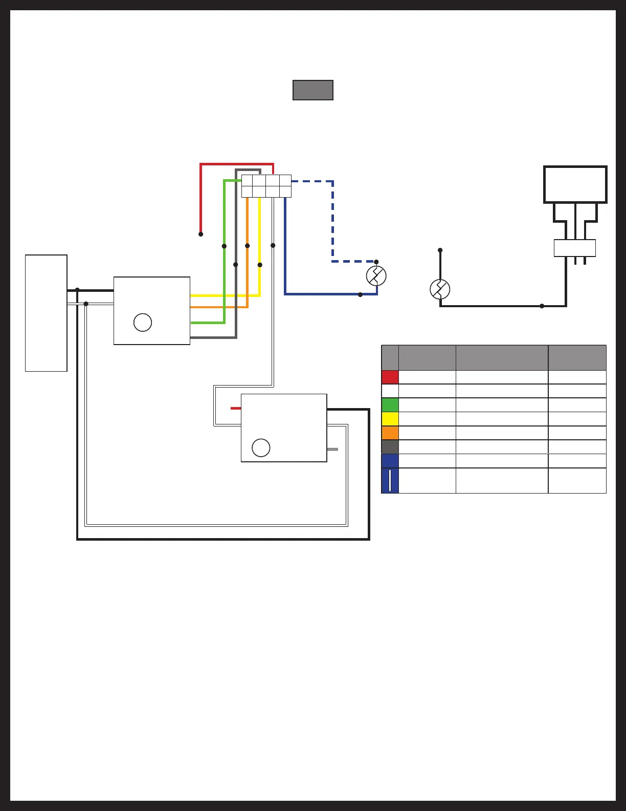
Fig. 9
OneControl® HVAC Triple Zone Wiring Diagram
Furnace, AC, Heatpump, Dual-speed Fan
Generator
(optional)
1 2 3
4 5 6
Zone Connector (715845 Controller)
T
T
THERM
T
T
THERM
Breaker Box
AC Hot
AC Neut
AC Hot
AC Neut
Gnd
Gnd
12V to Zone
12V to Zone
Compressor
Rev. Valve
High Fan
Low Fan
Heat Demand
LP Gas Supply
Zone T Sense
Outdoor T Sense (optional)
Color Signal
Zone
Connect
Red
Common
6
White Gas Heat 2
Green High Fan 8
Yellow Compressor 3
Orange Rev. Valve 4
Gray Low Fan 7
Blue Zone Temp Input 1
Sensor Power
5
Blue
w/stripe
8 7 6 5
4 3 2 1
OEM will connect red common wire
to 12v+ or 12v- (ground) depending
on manufacturer of AC unit.