tv
4
lci1.com 574-537-8900 Rev: 02.10.20
CCD-0002548
SolidStep
®
3.0
Adjustable Latch
Installation and Owner’s Manual
(For Aftermarket Applications)
Installation
Place Assembly Inside Doorframe
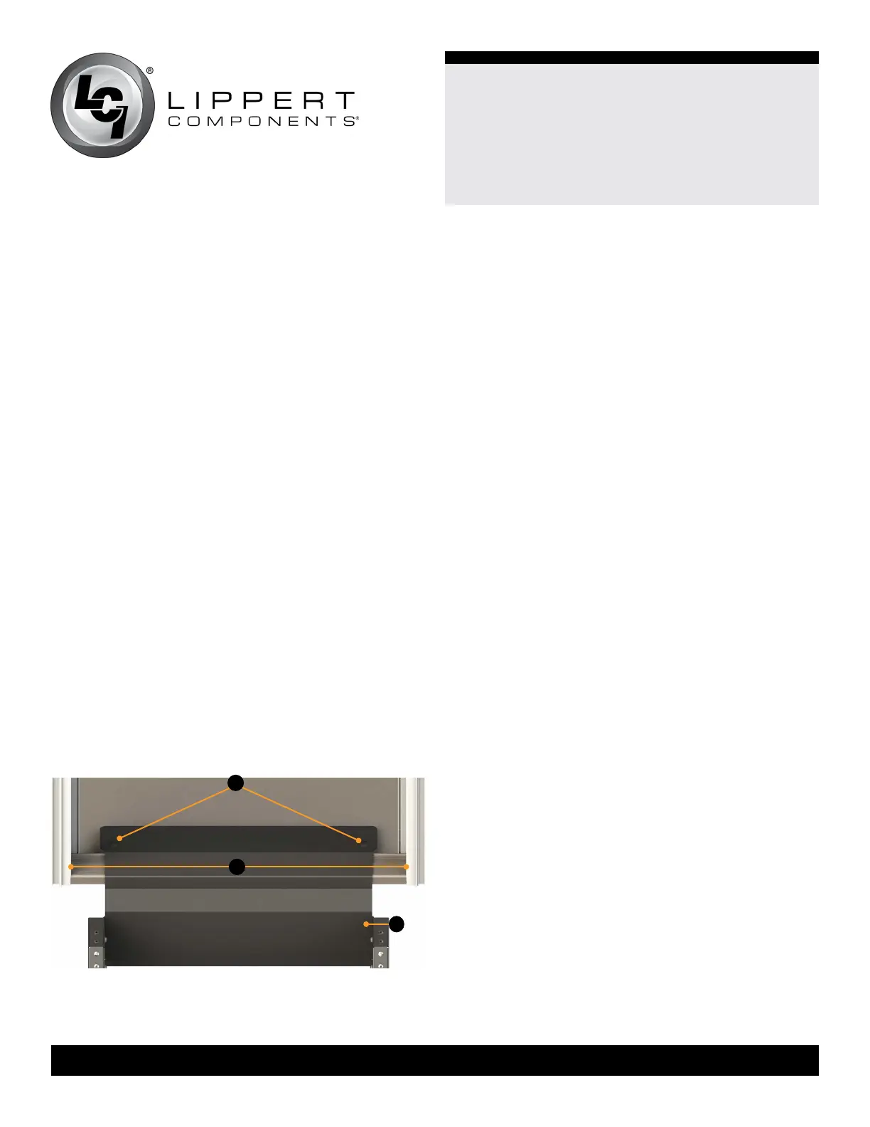
1. With the step extended and in the down position, place
the SolidStep assembly inside the doorframe (Fig.2).
NOTE: Before installing any fasteners, make sure that
the step is properly leveled so the threshold of the step
rests rmly on top and in front of the aluminum doorframe
threshold, without any gap between them. The rear of the
step wall (Fig.2C) should be approximately parallel with the
trailer’s sidewall in this position. Refer to Leg Extension
Adjustment section.
2. Verify with a tape measure that the assembly is centered
in the doorframe. Measure from frame to frame (Fig.2A).
B
A
Fig.2
3. With the step assembly still in the extended position,
install two fasteners.
NOTE: Most trailers use ooring construction that is
suciently strong to support a SolidStep with a simple
wood screw installation. Generally, if the ooring contains
a wood suboor thickness of at least
½”, method A may
be used. If unsure of your suboor thickness, or are
otherwise aware that the oor has a foam-laminated core
construction and only a thin wood suboor (sometimes
used for weight savings), then method B should be used.
This optional installation method connects the SolidStep
hinge plate to a strong steel backing plate which gets
placed underneath the oor, to ensure maximum oor
support.
A. For wood ooring, drill pilot hole using the ⁄ ” drill bit
and install two #10-1 ½” wood screws into the mounting
plate via the two access holes located in the top of the
mounting plate (Fig.2B).
B. For laminate ooring, drill two holes straight down
with the ⁄” drill bit via the access holes located in the
top of the mounting plate. Insert two #10-4” bolts into the
mounting plate through the oor through the backer plate
(Fig.2B) and secure with the plain washers, lock washers
and then the nuts provided. Refer to Figure 6 and Figure 7
for backer plate info.
4. Once the two fasteners are secure, carefully lift the step
assembly into the upright, stored position. If the latching
mechanism doesn’t engage, it will need to be adjusted to
operate properly. Have one person hold the step assembly
from inside the trailer. Go to Adjust Transport Lock section.
Prior to Installation
1. Make sure that the trailer is on level ground.
2. If the trailer oor has a step threshold transition piece, it
should be removed now.
NOTE: The door and frame have been omitted from gures
for clarity.
3. Make sure the oor of the trailer has sucient backing
material for securing the SolidStep. If uncertain, check
with the trailer’s manufacturer for backing material and its
location or use the backer plate and fasteners provided.
C

 Loading...
