EasyManua.ls Logo

Lippert 2022016064 - User Manual

Default Icon
24 pages
Print Icon
To Next Page IconTo Next Page
Loading...
1
lippert.com 432-LIPPERT (432-547-7378) Rev: 08.29.22
Quick Drop Stabilizer
Installation and Owners Manual
(For Aftermarket Applications)
CCD-0004455
Quick Drop
Stabilizer
Installation and
Owners Manual
(For Aftermarket Applications)
Quick Drop Stabilizer KitsQuick Drop Stabilizer Kits
Part #Part # DescriptionDescription
2022016064 Single Leg Kit
2022016065 Double Leg Kit
Table of Contents
Introduction ............................................ 2
Safety ................................................... 2
Parts List ................................................ 3
Installation (2 Legs, Center Piece) .................... 4
Resources Required ................................... 4
Preparation ............................................ 4
Determine Stabilizer Locations ........................ 4
Measuring Frame and Adjusting Assembly Width ..... 5
Attaching Stabilizers ................................... 9
Installation (1 Leg, Angled Application) ............ 10
Resources Required ................................. 10
Preparation .......................................... 10
Determine Stabilizer Locations ...................... 10
Attaching Stabilizers ................................. 11
Installation (1 Leg, Straight Application) ........... 13
Resources Required ................................. 13
Preparation .......................................... 13
Determine Stabilizer Locations ...................... 13
Attaching Stabilizers ................................. 14
Additional Information
............................... 16
Component Identication ............................ 16
Proper Stabilizer Position ............................ 17
Operation ............................................. 19
Resources Required ................................. 19
Preparation .......................................... 19
Extending Stabilizers ................................ 19
Retracting Stabilizers ................................ 20
Maintenance .......................................... 22
Troubleshooting ...................................... 22
Notes .................................................. 23
Question and Answer IconNeed help?

Do you have a question about the Lippert 2022016064 and is the answer not in the manual?

Overview

The Quick Drop Stabilizer is a device designed to enhance the stability of trailers, particularly travel trailers, by providing additional support points. It is available in two main configurations: a single leg kit and a double leg kit, catering to different trailer needs. The single leg kit (Part # 2022016064) is suitable for trailers that utilize a rear stabilizer only, while the double leg kit (Part # 2022016065) is intended for trailers with both front and rear stabilizers.

Function Description

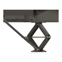
The primary function of the Quick Drop Stabilizer is to prevent unwanted movement and sway of a parked trailer, thereby improving safety and comfort. It achieves this by extending support legs from the trailer frame to the ground, creating a stable base. The device is designed to be quickly deployed and retracted, making it convenient for users. It works by distributing the trailer's weight evenly, which is crucial for optimal stabilization. The visual gauge on the stabilizer helps users determine if the leg is positioned at an angle sufficient to adequately stabilize the trailer.

Important Technical Specifications

The Quick Drop Stabilizer system includes various components, each with specific technical details:

  • Single Leg Kit (2022016064) Components:

    • Quick Drop Stabilizer: 1 unit
    • Flange Bolt, 3/8" - 16 x 1": 1 unit
    • Self-drilling Screw, 1/4" - 14 x 1": 1 unit
    • Flange Nut, 3/8" - 16: 1 unit
    • Nylon Locking Flange Nut, 1/4" - 20 (spare): 3 units
    • Washer, 1/4" (spare): 1 unit
    • Self-drilling Screw, 3/8" - 12 x 1": 3 units
    • Temporary Alignment Rod (T.A.R.) (spare): 3 units
  • Double Leg Kit (2022016065) Components:

    • Quick Drop Stabilizer: 2 units
    • Flange Bolt, 3/8" - 16 x 1": 2 units
    • Self-drilling Screw, 1/4" - 14 x 1": 2 units
    • Flange Nut, 3/8" - 16: 2 units
    • Nylon Locking Flange Nut, 1/4" - 20: 6 units
    • Washer, 1/4": 2 units
    • Self-drilling Screw, 3/8" - 12 x 1": 6 units
    • Temporary Alignment Rod (T.A.R.): 3 units
    • Center Piece: 1 unit
  • Required Resources for Installation:

    • Cordless or electric drill or screw gun
    • Torque wrench
    • Clamps
    • Appropriate drive bits
    • 5/16" drill bit
    • 25/64" drill bit
    • Tape measure
    • 1 to 2 people for installation

The stabilizer legs are designed to be mounted at specific locations on the trailer frame to ensure optimal stability. For the center piece installation, measurements are taken from the outside of the frame flange to the outside of the frame flange on the other side. The width of the entire assembly can be adjusted by moving the stabilizers in-and-out of the center piece. The slots on the center piece channel accommodate wide and short configurations, allowing for flexibility in installation based on the trailer's dimensions.

Usage Features

The Quick Drop Stabilizer is designed for ease of use, with clear instructions for both installation and operation.

  • Installation:

    • Preparation: Before installation, the trailer must be parked on level ground with wheels chocked. The manufacturer recommends lifting the trailer according to the manufacturer's recommendation using a properly-rated floor jack to safely work underneath the trailer. Support framework in accordance with the manufacturer's recommendation is also advised. Any underbelly material that might interfere with the installation must be peeled back.
    • Determining Stabilizer Locations: The rear stabilizer can be mounted at any point between the rear axle hanger and the bumper, while the front stabilizer can be mounted anywhere as long as the system remains within the approach angle. The approach and departure angles are determined by running a string line from the meeting point of the tire and ground up at an angle to the lowest point on the front and rear of the trailer.
    • Measuring Frame and Adjusting Assembly Width: The width of the assembly is adjusted to accommodate the trailer's overall width. The frame flange width is measured, and the overall width of the stabilizer assembly is adjusted accordingly.
    • Mounting: The stabilizer legs are attached to the trailer frame using mounting brackets, bolts, and self-drilling screws. The Temporary Alignment Rods (T.A.R.s) are used to slide the stabilizer into the center piece, ensuring proper alignment. Nylon locking flange nuts are used to secure the components.
    • Attaching Stabilizers: The stabilizer mounting brackets should be equally spaced out and outward from the frame as determined by the center mounting hole.
  • Operation:

    • Deployment: To deploy the stabilizer, a 3/4" socket on a ratchet or cordless drill is used to turn the hex coupler clockwise, lowering the footpad to the ground.
    • Retraction: To retract the stabilizer, the hex coupler is turned counterclockwise, lifting the footpad off the ground.
    • Optimal Positioning: The visual gauge on the stabilizer helps determine the optimal angle for stabilization. An inner arm and assembly body greater than a 90-degree angle indicates good positioning, while an angle less than 90 degrees suggests bad positioning. The goal is to achieve a 90-degree angle for optimal stability.
    • Safety Precautions: Users are warned not to lift the trailer completely off the ground with the stabilizers, as this can create an unstable condition. People and pets should be clear of the trailer while operating the stabilizers. Over-tightening the hex coupler is also cautioned against.

Maintenance Features

Regular maintenance is crucial to ensure the longevity and proper functioning of the Quick Drop Stabilizer.

  • Cleaning: It is recommended that when operating in harsh environments, such as heavy dust, salt, or ice buildup, the moving parts be kept clean. They can be washed with mild soap and water.
  • Lubrication: The ACME screw, a key component, is pre-coated with lubricant. If the screw is cleaned, it may be necessary to add any type of lithium-based lubricant to the screw to ensure smooth stabilizer operation. It is recommended to lubricate the screw yearly to ensure ease of use and preventively protect the system's longevity.
  • Troubleshooting:
    • Hex coupler is difficult to turn: This issue is typically caused by debris in the mechanism. The recommended solution is to remove debris and clean the mechanism with mild soap and water, then apply a light coating of lithium-based lubricant to the ACME screw and pivot points.
    • Spring latch is cracking: This indicates too much stress on the system. To resolve this, use Quick Drop Stabilizers to balance weight to avoid damage to the stabilizers or trailer. If the spring latch is cracked, it should be replaced.

The Quick Drop Stabilizer is a robust solution for enhancing trailer stability, designed with user convenience and safety in mind, and supported by clear installation, operation, and maintenance guidelines.

Lippert 2022016064 Specifications

General IconGeneral
BrandLippert
Model2022016064
CategoryIndustrial Equipment
LanguageEnglish

Related product manuals