18
lippert.com 432-LIPPERT (432-547-7378) Rev: 08.29.22
Quick Drop Stabilizer
Installation and Owner’s Manual
(For Aftermarket Applications)
CCD-0004455
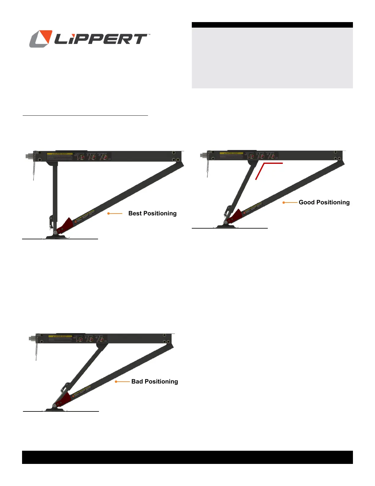
Examples of Quick Drop Stabilizer Positioning
The following figures show examples of the Quick Drop
Stabilizer from optimal to inadequate stabilization.
Fig.31
Fig.32
BEST: Optimal Stabilization is achieved when the inner
arm and Quick Drop leg clear the visual gauge AND the
inner arm and assembly body are almost at a 90 degree
angle (Fig.31).
NOTE: Upon completion, the inner arm should not have
moved beyond a 90 degree angle; perpendicular to the
assembly body. Doing so may cause the mechanism to
bind and cause damage.
GOOD: Adequate Stabilization can be achieved with the
inner arm and assembly body greater than a 90 degree
angle, BUT the inner arm is clear of the
visual gauge (Fig. 32).
NOTE: The GOOD position (Fig. 32) is recommended for
preloading so that the stabilizer can be extended and finish
in the BEST position (Fig. 31) (90 degree angle).
BAD: Stabilization is inadequate when the inner arm
and Quick Drop leg ARE NOT clear of the visual gauge.
The angle of the inner arm and assembly body is too great
to assure that the trailer weight can be
evenly distributed (Fig. 33).
Best Positioning
Good Positioning
Fig.33
Bad Positioning
NOTE: The black line represents the ground in relation to
the Quick Drop Stabilizer.