Do you have a question about the LiteOn EVO6000 Series and is the answer not in the manual?
Introduces the EVO6000 Series Ultra Compact Vector Drive.
Identifies the specific product series covered in the manual.
Provides general safety information, warnings, and cautions.
Safety precautions related to the intended use of the drive.
Safety guidelines for receiving the drive.
Safety instructions for installing the drive.
Safety guidelines and warnings for wiring the drive.
Safety precautions during drive operation.
Safety instructions and warnings for drive maintenance.
Information about the warning label on the drive.
Precautions for using AC drives in applications.
Information about the product warranty.
Details on the warranty period.
Limitations and restrictions of the warranty.
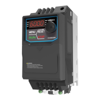
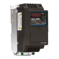
Identifies the various components of the drive.
Checklist for verifying the drive upon receiving.
Information found on the drive's nameplate.
Explanation of the EVO6000 series model number structure.
Tables detailing power ratings for different drive models.
General specifications applicable to the drive series.
Physical dimensions and diagrams of the drive.
Information about available accessories for the drive.
Lists specific accessories with their model names and descriptions.
Guidance on installing appropriate input fuses for the drive.
Specifications for the optimal operating environment for the drive.
Guidelines on drive orientation and clearance for airflow.
Recommended orientation for drive installation.
Required spacing around the drive for proper ventilation.
Steps for installing the keypad and terminal cover.
Methods for protecting the drive and cables from short circuits.
How to protect drive and input cables against short circuits.
Protection for motor and output cables against short circuits.
Critical safety warnings and precautions for wiring.
Details on the main circuit wiring of the drive.
Identification and description of main circuit terminals.
Instructions for wiring the main circuit.
Information on connecting a braking unit.
Guidelines for proper grounding of the drive.
Specifications for main circuit cable sizing and torque.
Overview of the drive's control circuit.
Identification and description of control circuit terminals.
Details on the drive's input terminals.
Details on the drive's output terminals.
Instructions for wiring the control circuit.
Cable sizing and torque specifications for control circuits.
Information and models for ferrule-type terminals.
How to connect input and output signals.
Setting the DIP switch for NPN/PNP input mode.
Selecting voltage or current input for terminal A1.
A checklist to ensure all wiring is done correctly.
Pre-operation checks to ensure safety and correct setup.
Steps for powering up the drive and understanding status displays.
Overview of the drive's keypad functions.
Identification and function of keypad keys and displays.
Information about the LED display characters on the keypad.
Table showing LED display characters for numbers and letters.
Explanation of the drive's LED indicator lights.
How to navigate and program using the keypad.
A comprehensive list of drive parameters and their settings.
Section for initialization parameters and basic settings.
Parameters related to drive application settings.
Settings for selecting the drive's operation mode.
Parameters for configuring DC braking functionality.
Parameters for enabling and configuring speed search.
Parameters for configuring timer functions.
Parameters for setting up and tuning PID control loops.
Section for drive tuning parameters.
Parameters for acceleration and deceleration time settings.
Parameters for configuring S-curve acceleration/deceleration.
Parameters for adjusting torque compensation.
Parameters for slip compensation settings.
Parameters for setting the carrier frequency.
Parameters for Sensorless Voltage Vector Control.
Parameters related to frequency command settings.
Configuration of multi-step frequency commands.
Settings for upper and lower limits of frequency commands.
Parameters to set jump frequencies for resonance avoidance.
Settings for frequency command hold and Up/Down 2 command.
Section for configuring motor parameters.
Parameters for setting the V/F curve characteristics.
Parameters for motor identification and characteristics.
Configuration for multi-function I/O terminals.
Settings for digital input terminals S1 through S6.
Settings for multi-function digital outputs.
Settings for analog input terminal A1.
Settings for analog output terminal FM.
Configuration for optional communication cards.
Section for drive protection parameters.
Parameters for motor overload and protection functions.
Settings for handling momentary power loss events.
Parameters for preventing motor stall during operation.
Parameters for frequency detection functions.
Settings for automatic fault restart attempts.
Parameters for detecting overtorque and undertorque conditions.
Parameters for various drive protection features.
Section for keypad function settings.
Settings for display units and format on the keypad.
Settings for multi-function selection on the keypad.
Settings related to drive maintenance tracking.
Section for auto-tuning parameters.
Parameters for performing auto-tuning of the motor.
Section for optional drive functions.
Parameters for pump control and water shortage detection.
Section for drive monitor settings.
Monitors for displaying drive status and input/output signals.
Displays detailed information about recent drive faults.
Monitors for tracking drive operation and maintenance data.
Monitors related to PID control loop performance.
Lists alarms and faults, their causes, and possible solutions.
Identifies fault codes, causes, and possible solutions.
Lists operation errors, their causes, and solutions.
Details auto-tuning faults, causes, and troubleshooting steps.
| Form Factor | M.2 2280 |
|---|---|
| NVMe | Yes |
| Operating Temperature | 0°C to 70°C |
| Storage Temperature | -40°C to 85°C |
| Interface | PCIe Gen3 x4 |
| Capacity | 480GB, 960GB |
| NAND Type | TLC |
| Shock Resistance | 1, 500G, 0.5ms |
| Vibration Resistance | 20G (10~2000Hz) |