- 14 -
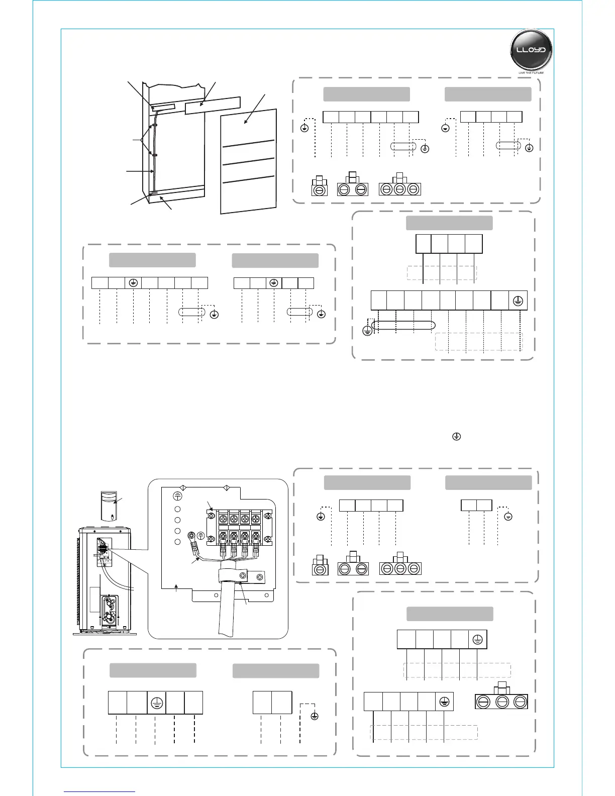
Connector
To power source
2
1
4
5 N L
Heat pump Type
Yellow
/Green
2
1
4
5
1
2
N
Cold wind Type
To power source
Yellow
/Green
1
2
Cover
Power wire
Terminal board
Fastener for
cable connection
Supporting
plate for foamy shell
Input bar
Plastic strap
N(2)
1
4
5 N L
Heat pump Type
To power source
Red
Yellow
/Green
Black
Blue
Brown
1 N(2)
N L
L
Cold wind Type
To power source
Yellow
/Green
Red Black
L1 L2 L3
N
12000W
L1 L1L2 L2L3 L3
N N
Yellow
/Green
To power source
L1 L2 L3
N
L1 L2 L3
N
L
Outdoor Unit
★
●
●
●The grounded wire connection:
1.loosen the grounded screw of electrical shelf.
2.Connect the grounded wire with the grounded screw then setscrew in the“ ”mark formerly.
●
●
Unscrew the screw, take off the control panel cover from the unit.
Connect the cable to their terminals according to their number or colors.
Fix the cable to the terminal board with fastening piece.
Reinstall the cover with the screw.
Cover
1
2
L
N
1
2
5
4
Fastener for cable
connection
shelf
Grounded wire
Terminal board
Interconnection cord
More than 5mm
Connector
2
1
4
5
Heat pump Type
Yellow
/Green
2
1
4
5
1
2
Cold wind Type
Yellow
/Green
1
2
Heat pump Type
Cold wind Type
12000W
L1
L2
L3
N
Red
Green
Brown
Blue
Yellow/Green
1
N(2)
1 4
5
Red
Black
Yellow
/Green
Red
Black
Yellow
/Green
Blue
Brown
N(2)
Connector
Red
Green
Brown Black
Red
Green
Brown
Blue
Yellow
/Green
L1
L2
L3
N
Yellow/Green
L1
L2
L3
N
Red
Green
Brown
Blue
Yellow/Green
L1
L2
L3
N
Yellow/Green