Do you have a question about the LNS HYDROBAR SPRINT S3 and is the answer not in the manual?
Describes the manual's layout, page numbering, and navigation elements.
Outlines copyright, reproduction, and liability limitations for the manual.
States the product's conformity with relevant directives and standards.
Essential guidelines for safe operation, handling, and maintenance.
Details the safety mechanisms and their functions to prevent accidents.
Lists key technical specifications, dimensions, and performance data.
Provides dimensions and layout information for installation purposes.
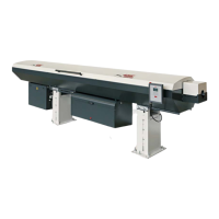
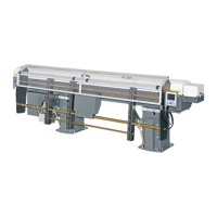
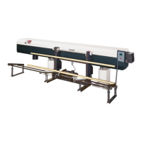
Illustrates and identifies the main components and their arrangement.
Outlines prerequisites and initial steps before installation.
Details the process of unpacking and assembling the unit.
Specifies air pressure, consumption, and connection procedures.
Guides the user on how to align the bar feeder with the lathe.
Explains the procedure for securing the unit to the floor.
Describes the steps for assembling the bar loader component.
Introduces the electrical components and international standards.
Details the layout and components within the main electrical cabinet.
Explains the PLC's role and its input/output functions.
Presents schematics for the complete electrical system.
Covers the connection and communication interface with the lathe.
Explains how to adjust air pressure for optimal system performance.
Presents circuit diagrams for the pneumatic system.
Describes the hydraulic components and their specific functions.
Presents the schematic of the hydraulic circuit.
Covers requirements and methods for preparing bar stock for feeding.
Details the process of changing components for different bar diameters.
Explains how to adjust gear ratios for pushing force.
Describes the replacement of spindle reduction tubes.
Outlines the procedure for changing guiding elements.
Explains the functions and use of the remote control unit.
Details the procedures for turning the system on and off.
Describes the automatic operation sequence and required checks.
Covers configuration parameters and adjustments for specific operations.
Provides guidance on routine maintenance tasks for the system.
Lists available spare parts with part numbers and descriptions.
| Manufacturer | LNS |
|---|---|
| Voltage | 400 V |
| Type | HYDROBAR SPRINT S3 |
| Model | S3 |
| Bar Capacity | 3 bars |
| Bar Length | 1600 mm |
| Feed Rate | 600 mm/s |
| Frequency | 50 Hz |
| Magazine capacity | 3 bars |