Do you have a question about the LNS ALPHA SL65 S and is the answer not in the manual?
Describes maintenance and setting procedures for the bar feeder.
Identifies target audience: service technicians and manufacturers.
Mentions integrated components from other manufacturers and compliance.
LNS's responsibility for transport damage.
Explains conventional terms and symbols used in the manual.
States reproduction restrictions and LNS's liability limitations.
Provides essential safety guidelines for operating and maintaining the bar feeder.
Step-by-step instructions for safely lifting the bar feeder.
Instructions for mounting the X-axis retraction system.
Instructions for mounting the Z-axis retraction system.
Guidelines for positioning the bar feeder relative to the lathe.
Instructions for leveling the bar feeder, including different systems.
Procedures for aligning the bar feeder with the lathe.
How to adjust the bar feeder's center to match the lathe spindle center.
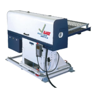
Instructions for mounting the magazine onto the bar feeder.
Steps to securely anchor the bar feeder to the floor.
Procedure for replacing or changing the pusher assembly.
How to set the bar feeder for automatic or manual operation sequences.
Steps to initiate a new machining cycle.
Detailed steps for operating the bar feeder in automatic mode.
How to switch the bar feeder from automatic to manual mode.
Adjusting the stopping fingers for proper bar loading.
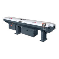
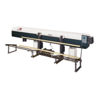
Description and layout of the bar loading system.
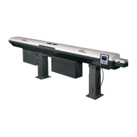
Description and layout of the bar feeding system.
Details on the transmission unit and its components.
Information about the pusher assembly and available diameters.
Explanation of the V channel set and its operating positions.
How to adjust the channel's upper position based on bar stock diameter.
Explains the function and material of spindle liners.
Diagram showing the pneumatic components.
Details on the F.R.L. unit and its functions.
Steps to adjust the pneumatic service pressure.
Description and layout of the solenoid valve manifold.
How to manually operate pneumatic cylinders.
Explains the function of the air pressure switch.
Identifies components ensuring safe operation of the bar feeder.
Details the function and wiring of various safety switches.
Lists and identifies key electrical components with designations.
Layout of components within the electrical cabinet.
Function of the main disconnect switch and circuit breaker.
Operation of the K1 electromagnetic switch in the E-stop loop.
Overview of the remote control interface and its functions.
Details command keys, numerical keypads, and display functions.
Describes the various function keys and their operations.
How to access and interpret parameters and messages on the HMI.
Function of the servo amplifier in controlling the servo motor.
Information about safety relays and their role.
Details on transformers and the analog module for servo motor control.
Explains the PLC's role in processing signals and controlling operations.
Description of the PCB and its accessory components like motors and sensors.
Function of the measuring cell and power supply/cable connections.
Details on signals exchanged between lathe and bar feeder.
Most frequently changed parameters for controlling the bar feeder.
How to access and navigate the operation parameter screens.
A quick overview of operation parameters, their descriptions, and access.
Detailed explanation of adjustable parameters within rectangles.
Setup for maximum and minimum feeding distance alerts.
Retraction position to avoid contact with the rotating spindle.
Defines bar stock needed for a part, torque, and chuck open times.
Pusher retracting distance to avoid spindle contact.
Position for the tip of a new bar after touching the TOP CUT switch.
Defines the limit for detecting the end of the bar stock.
Position for the pusher to eject the remnant in AUTO mode.
Forward limit and loading flag rapid distance setup.
Postponing signals/actions before/after chuck close/open.
Enables DRY RUN state for testing without manual input.
Defines how Top cut is positioned, using turret or pusher.
Selects how the bar is positioned for machining each part.
How to access the password-protected service parameters.
Lists service parameters, their descriptions, and access modes.
Detailed description of various MODE settings (1-4).
Simulates bar feeder operation without external control.
Defines chuck action based on CHUCK signal.
Processes lathe auto signal for pusher actions.
Controls loading cycle based on START LOADING signal.
Allows lathe to control bar feeding forward.
Defines approach for initiating bar loading.
Defines safety check for operation status.
Defines PLC output Y05 action during production.
Defines End of Bar signal output action.
Setups for bar feeding and remnant ejection.
Sets servo motor turning speeds (RPM) for different operations.
Option to select language, default is English.
Function to assist pushing bars through the chuck.
Checks part length after a set number of parts are completed.
Defines units for length parameters on HMI.
Tests the connection between bar feeder and lathe.
Deactivates maximum acceptable bar stock feeding distance.
Sets forward limit based on P08 or P06 setup.
Verifies bar stock position before switching to automatic mode.
Defines A4 signal as pulse or continuous ON.
Defines lathe door action upon receiving lathe door signal.
Schedule for periodic checks of various components.
How to check and drain the condensate collector.
How to check and refill the oil in the lubricator.
Procedures for cleaning the bar feeder's exterior and interior.
Lists the specifications and dimensions of the bar feeder.
Procedures for decommissioning and recycling the machine.
Lists common warning messages and their solutions.
Flowchart illustrating error messages and machine actions.
Details PLC alarms, their causes, and corrective actions.
Lists operational sequences and associated alarms.
Lists error codes from the servo amplifier and their meanings.
Comprehensive table of servo amplifier fault codes and descriptions.
Detailed causes and solutions for specific alarms.
Diagram showing PLC inputs and outputs and their functions.
How to access product information via QR code and Dropbox.
Contact information for customer service and parts.
Definitions of technical terms used in the manual.
Electrical wiring diagram for the BSL65 A8 model.
Schematic diagram of the pneumatic system.
A form for ordering parts or services.
| Brand | LNS |
|---|---|
| Model | ALPHA SL65 S |
| Category | Industrial Equipment |
| Language | English |