Do you have a question about the LNS SERVO S3 T and is the answer not in the manual?
Explains page numbering, chapter titles, and model identification.
Explains how reference numbers are shown with LNS ordering numbers and how chapters refer to each other.
Explains warning signs, notes for safety, and operational guidance.
Covers copyright, liability for use, and trademark information.
Declares compliance with EU directives and lists harmonised standards used.
Provides crucial safety guidelines for installation, maintenance, and operation.
Explains safety covers, switches, and emergency stop functions.
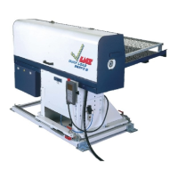
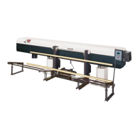
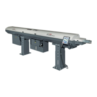
Identifies key components and their designations on the bar feeder.
Lists weight, dimensions, capacities, power, and performance data.
Provides space requirement information for installing the bar feeder.
Shows technical drawings for various loading configurations (rear/front, transverse/longitudinal).
Identifies and describes various components of the bar feeder.
Details delivery methods (pallet/crate) and provides unpacking instructions and safety precautions.
Instructions for lifting, moving, and positioning the bar feeder for installation.
Steps for assembling the bar magazine and adjusting its position.
Instructions for assembling and setting the bar length limiters.
Details assembly and operation of the retraction system for moving the bar feeder.
Procedures for adjusting bar feeder height and aligning it with the lathe.
Explains the need for anchoring and the provided anchorage points.
Points to consider for safe assembly and integration of the unit.
Refers to relevant chapters for electrical and pneumatic connection details.
Introduces the chapter on electrical circuits and components.
Identifies electrical components like remote control, cabinet, and safety switches.
Details the layout and components within the electrical cabinet.
Explains the function, connection, and protection of transformers and servo amplifiers.
Explains the PLC's function, modules, and battery status.
Lists and describes PLC signals and presents electrical diagrams.
Details interface requirements, power supply, and signals between lathe and bar feeder.
Details pneumatic components and mandatory pressure requirements.
Describes the air unit, its connections, and pressure setting procedure.
Details pneumatic battery elements, layout, and manual activation.
Explains the function and setting procedure for the pressure control unit.
Presents symbols and pneumatic circuit diagrams.
Describes bar magazine capacity, features, and limiter adjustment.
Recommendations for loading bars of varying lengths and orientations.
Using the feeder for parts like piston rods and adjusting rear limiter.
Notes on additional settings and accessories required for profiled bar loading.
Explains the loading table's functions and the calibration procedure.
Explains the servo motor and carrier system for the loading pusher.
Explains pusher types, ranges, layout, and replacement procedure.
Step-by-step guide for replacing the pusher and setting the mechanical stop.
Describes methods for loading tubes and instructions for belt tensioning.
Explains the retraction system's purpose, types, and operation.
Details optional kits for square bars and quick part loading.
Instructions for powering the bar feeder on/off, and remote control interface overview.
Explains the display screen elements and the meaning of available icons.
Describes multi-function, direction, emergency stop, and mode buttons.
Outlines job preparation and pusher change for different bar types.
Procedures for adjusting loading stops for profiled and round bars.
Discusses collet types, chuck grip, and the use of reduction tubes.
Details parameters for adapting the bar feeder and accessing setting functions.
Covers setting part diameter, shape, length, and top-cut position.
Parameter to save time when loading new bars of the same length.
Parameters for feed rate adaptation and application setup modes.
Modes for part feed out via sub spindle and loading with extended pusher.
Covers misc. applications, torque settings, and language selection.
Settings for End of Bar Position and Top-Cut Position.
Explains the parts library for storing and recalling part parameters.
Details service parameters and how to access help screens.
Shows the status of current input and output signals used in the barfeed.
Displays alarm history and helps monitor memory list and bits.
Provides a sequential diagram for the automatic cycle of the bar feeder.
Explains and details the setting procedures for End of Bar and Top-Cut positions.
Lists PLC alarms, their descriptions, and corresponding solutions.
Details alarms for low air pressure, switch faults, and table raising issues.
Details alarms for switch/probe faults and table lowering issues.
Details alarms for probe activation, magazine empty, and cycle interruptions.
Details alarms related to lathe collet, feed out, and M-code synchronization.
Details alarms for pusher faults, communication errors, and simulation issues.
Details alarms for part ID, file errors, motor issues, and configuration mismatches.
Details alarms for amplifier status, communication, and firmware compatibility.
Lists servo amplifier alarm codes, errors, and deactivation methods.
Covers maintenance for pneumatics, batteries, belt, and cleaning.
A form to be filled out for ordering spare parts or devices.
Provides an example of programming for lathe integration.
Lists contact websites for LNS Europe, America, and Asia.
| Brand | LNS |
|---|---|
| Model | SERVO S3 T |
| Category | Industrial Equipment |
| Language | English |