Do you have a question about the LNS Alpha 538 and is the answer not in the manual?
Explains manual structure, cross-references, captions, and defines warning symbols.
Covers copyright, reproduction rights, and LNS disclaimers for product use.
Details machinery compliance with European directives and harmonized standards.
Provides essential safety guidelines for operating and maintaining the bar feeder.
Outlines safety strategies, risk assessment, and protection methods for correct incorporation.
Lists key technical specifications like weight, dimensions, and capacities.
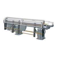
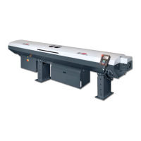
Provides diagrams illustrating the physical layout of the bar feeder and lathe.
Identifies and describes the main components and their designations.
Details safe transportation methods and procedures for unpacking the bar feeder.
Instructions for preparing the machine for mounting, including lifting and positioning.
Guides on aligning the bar feeder correctly with the lathe for optimal operation.
Steps for securely anchoring the bar feeder to the floor for stability.
Instructions for connecting the bar feeder's electrical system to the lathe.
Details on connecting the pneumatic supply and setting the pressure.
Information on hydraulic oil, connections, and filling procedures.
Describes the electrical parts of the bar feeder and relevant international codes.
Diagram and table identifying electrical components and their article numbers.
Details the components within the electrical cabinet and their designations.
Details circuit breaker QF2, transformers T1/T2, and the PCB.
Explains the servo amplifier, PLC, and PLC input/output mapping.
Provides schematic diagrams for the bar feeder's electrical system.
Lists pneumatic elements and pressure requirements for optimal operation.
Diagram and table identifying pneumatic components and their designations.
Describes the Filtering-Regulation-Lubrication unit and its settings.
Explains the pneumatic valve battery and lists its components.
Details the air pressure switch and manual operation of pneumatic valves.
Guides on checking the condensate collector and lubricator for the pneumatic system.
Provides schematic diagrams for the pneumatic control circuits.
Describes the hydraulic system concept and lists its main components.
Diagram and table identifying hydraulic components and their article numbers.
Details the hydraulic pump motor and oil pressure switch, including adjustment.
Instructions for filling the hydraulic tank and recommended maintenance practices.
Explains the bar feeder's loading ramp and bar stock installation.
Diagram and table identifying bar magazine components.
Procedure for manually adjusting the bar selection handle for diameter.
Explains the function of guiding elements and their role in bar support.
Diagram and table identifying guiding elements and their systems.
Chart for selecting guiding elements based on barfeed length and pusher type.
Step-by-step instructions for replacing guiding elements.
Explains the pusher's function and available lengths for remnant extraction.
Table for selecting pusher bodies, sleeves, adapters, and collets by diameter.
Describes fixed and telescopic tubes, including specifications for the telescopic system.
Explains the electronic synchronization for headstock movement replication.
Diagram and table identifying synchronization device components.
Details the chain drive operation, components, and procedure for chain tension adjustment.
Describes the vise function for remnant extraction and its components.
Step-by-step instructions for replacing worn remnant extraction clamping blades.
Explains the function of the pneumatic front rest for stock guiding.
Diagram and table identifying pneumatic front rest components.
Procedure for setting up the pneumatic front rest for open/closed positions.
Details the function and operation of the retraction system for maintenance access.
Describes the remote control interface, touch screen, and display functions.
Explains the functions of Emergency Stop, AUTO Ready, AUTO START, and Rightward buttons.
Details manual movement controls and functions for opening/closing the channel.
Step-by-step guide for powering on the bar feeder system safely.
Explains the function of emergency stop buttons on the cabinet and remote control.
Guides on starting a new machining cycle and continuing an interrupted one.
Instructions for accessing and editing operation parameters, focusing on part setup.
Details parameters for guiding channel, clamping openings, and application settings.
Explains M-code, deceleration, and position parameters for operation.
Covers front rest position, auxiliary end of bar, torque, and language settings.
Details unit selection, functions like unload, dry run, and front rest setup.
Covers service parameters for bar feeder length, position, pusher, and loading configuration.
Details advanced service settings for automatic halt, hydraulic pump, feed safety, and torque.
Covers service parameters for feed rates and system options like front rest type.
Details interface parameter status, clamping device delays, and additional I/O modules.
Covers service modes (working, simulation, test) and help sections for software versions.
Displays status of inputs, outputs, and counts end-of-bar cycles.
Details the automatic cycle for new loading, part feed out, and remnant extraction.
Details alarms for emergency line, main cover access, and barfeed working position.
Details alarms for oil pressure, air pressure, and switch failures.
Details alarms for switch failures during channel operation and measuring cell.
Details alarms for SQ2 switch, lathe cycle resumption, and loading time.
Details alarms for part feed out timing and length issues.
Details alarms related to headstock reverse, travel, and pusher stock loss.
Details alarms for insertion, extraction, and magazine status.
Details alarms for simulation mode, remnant length, and positioning errors.
Details alarms for front rest failure and interrupted loading/unloading cycles.
Details alarms for booster clutch engagement, disengagement, and insertion failures.
Details the alarm for booster failure during the extraction process.
Details alarms for motor reference loss, servo positioning errors, and servo driver faults.
Discusses installation, distance, alignment, spindle length, and gap issues affecting performance.
Covers bar properties, tubes, profiled material, straightness, and composition impacts.
Provides guidance on maintenance for hydraulics, pneumatics, batteries, mechanics, and cleaning.
Provides an example of a main and part program for lathe operation.
A template for ordering parts and accessories for the bar feeder.
Lists LNS regional websites for representatives and support.
| Brand | LNS |
|---|---|
| Model | Alpha 538 |
| Category | Industrial Equipment |
| Language | English |