CHAPTER 6: HYDRAULICS 6-3
ALPHA 538/552
2. DESCRIPTION OF THE ELEMENTS
2.1. Hydraulic pump motor
The hydraulic pump is powered by 3 phases 220V AC. The hydraulic pump powers on immediately when
conditions below satisfied:
- The bar feed system switched to automatic mode.
- The guide channel is closed.
- The pusher position is located between home position the “2nd” of parameter P06.
For further information, refer to “Chapter 3. SETTING INTO OPERATION” and “Chapter 4. ELECTRICS”.
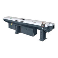
2.2. Oil pressure switch
The pressure is constantly monitored by a pressure
switch set at the factory at a point of release of 0.5
bar. There are 2 types of switches that were fitted to
the bar feeder. It may be adjusted, if necessary, as
follows:
Settings for square body style:
1. With a screwdriver, unscrew the locking
screw (A).
2. Insert a hex head wrench (5mm) into the
center of the pressure switch (B).
By turning clockwise, the release of the
pressure switch will take place at a pressure
higher than the original setting. Turning in the
opposite direction, will produce the reverse.
PLC input X12 will show the condition of the
switch, and can be monitored to assist for setting.
3. When the adjustment is completed, retighten
the locking screw (A).
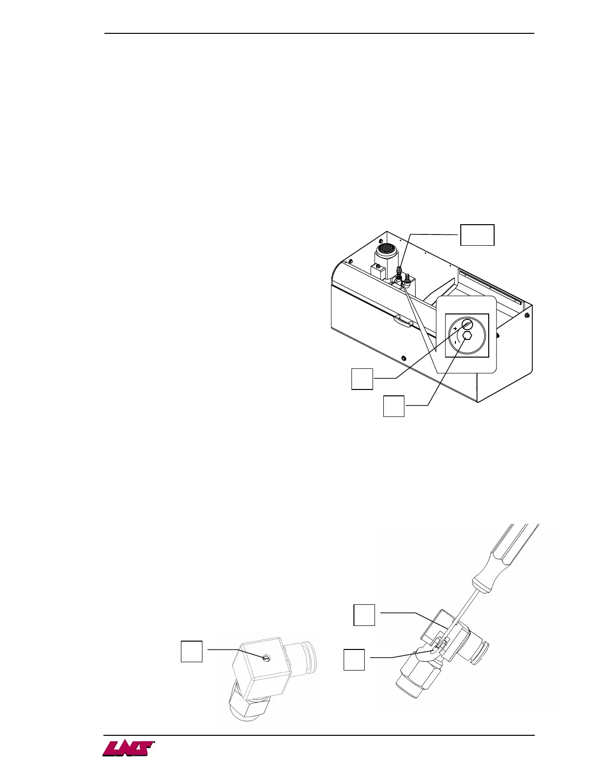
Settings for hex body style:
1. With a screwdriver, unscrew and completely remove the cap screw from
the plug, leaving the plug installed on the switch (C).
2. Insert a small diameter flat blade screwdriver (ø2-2.5mm) into the center
of the pressure switch (D) where the cap screw was located. The adjuster is
located inside the body of the switch (E). By turning
clockwise, the release of the pressure switch will take
place at a pressure higher than the original setting.
Turning in the opposite direction, will produce the
reverse. PLC input X12 will show the condition of the
switch, and can be monitored to assist for setting.
3. When the adjustment is completed, reinstall the cap
screw into the plug and tighten (C).
A
B
SP2
D
E
C