CHAPTER 6: HYDRAULICS 6-2
ALPHA 538/552
1. HYDRAULIC EQUIPMENT
Please read the safety instructions provided at the beginning of this manual before
handling the following devices.
1.1. Description
The guiding concept of the ALPHA 552 bar feeder consists mainly in maintaining the bar suspended in an
oil bath.
The hydraulic oil is contained in the machine itself. Aspirated by a pump motor, it is injected into the front
rest and the guiding blocks. A pressure switch measures the pressure at the outlet of the pump.
A level allows the monitoring of the filling rate of the hydraulic tank.
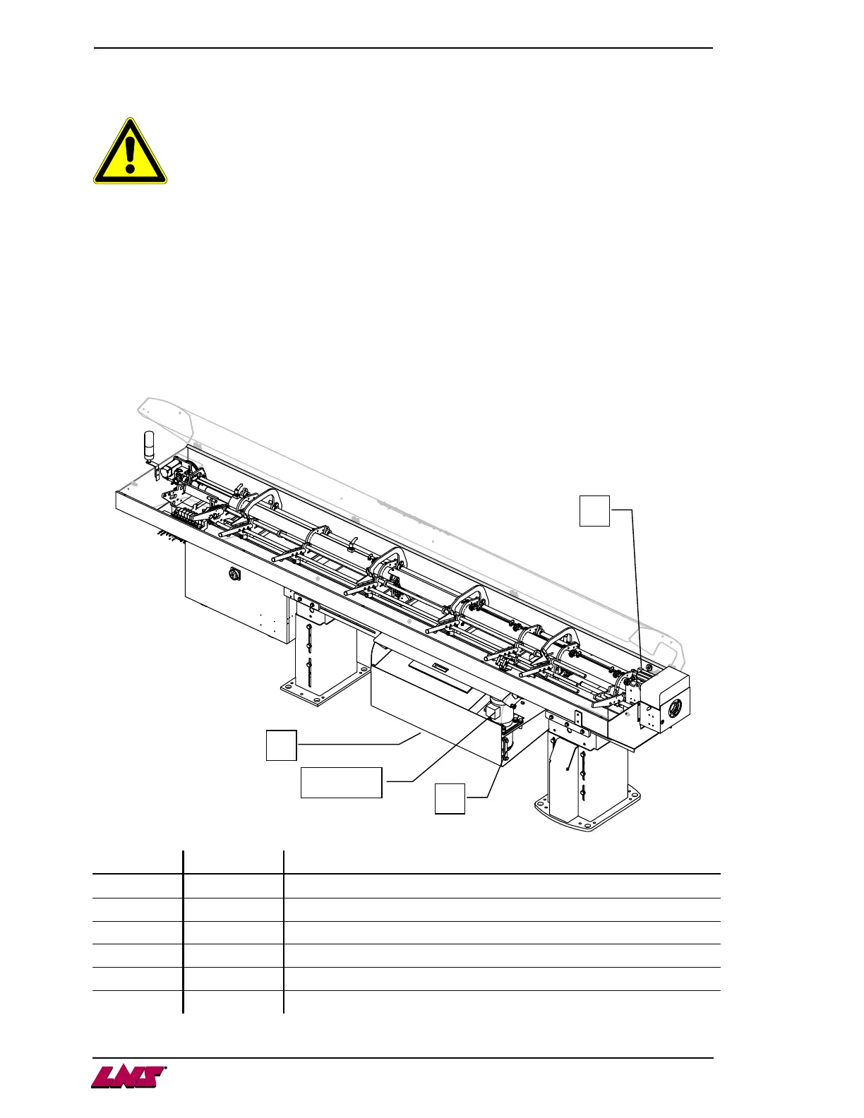
1.2. Layout of the elements
Designation
Article No Description
A C17110500 Level
B - Guiding blocks supply tube (not shown here)
C - Front rest supply tube
D C17120400 Drain plug
M1 X51.09.P017A
Hydraulic pump motor
SP2 44.0179.K0.15
Oil pressure control switch
A
C
D
M1 / SP2