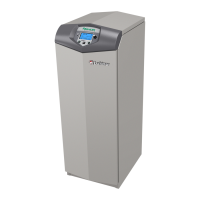
Do you have a question about the Lochinvar Armor X2 AWN1300 and is the answer not in the manual?
Immediate actions and contact procedures for gas leaks.
Explains DANGER, WARNING, CAUTION, and NOTICE symbols.
Emphasizes manual reading, annual service, and safety precautions.
Warns against installing in rooms with corrosive contaminants.
Details the function of various internal and external parts.
Lists model numbers, input, water, gas, and vent/air sizes.
Notes specific adjustments and ratings for high altitude models.
Lists codes, regulations, and pre-installation checks required.
Specifies required clearances for combustibles, service, closets, and alcoves.
Details requirements for room air openings and preventing contamination.
Specifies acceptable flooring and foundation considerations.
Lists contaminants to avoid and guidelines for using existing vent systems.
Procedures for safely removing a unit from a common vent system.
Details air supply requirements for equipment rooms via ducts or interior spaces.
Specifies minimum recommended combustion air supply to the equipment room.
Step-by-step instructions for safely removing the unit from its shipping pallet.
Illustrates sidewall and vertical direct venting configurations.
Instructions for installing vent and air piping, including materials and connections.
Details specific connection procedures for air intake and vent piping.
Specifies Canadian certifications and provides tables for vent/air piping sizes.
Provides guidance on sizing combustion air and vent piping based on model and length.
Lists acceptable materials for air inlet pipes and details sealing procedures for joints.
Discusses using room air for combustion and the risks of air contamination.
Details approved PVC/CPVC materials and installation procedures, including cementing.
Covers approved polypropylene vent manufacturers, adapters, and termination kits.
Outlines approved stainless steel vent materials, terminations, and adapters.
Provides guidelines for locating and terminating sidewall vents and air inlets.
Guidelines for selecting the optimal location for sidewall vent and air terminations.
Details minimum clearances for sidewall vent and air terminations from various building features.
Instructions for cutting holes and installing wall plates for sidewall terminations.
Instructions for preparing wall penetrations using alternate field supplied options.
Guidelines for terminating multiple sidewall vent/air connections.
Guidelines for locating and terminating vertical vents and air inlets on a roof.
Guidelines for selecting the optimal location for vertical vent and air terminations.
Instructions for cutting roof openings and installing penetrations for vertical venting.
Guidelines for terminating multiple vertical vent/air connections on a roof.
Covers basic piping steps, clearances, and the critical risk of scalding water.
Discusses water quality impact and details on piping components like check valves and unions.
Outlines procedures for connecting the gas supply, including sediment traps and purging.
Specifies pressure requirements for natural and propane gas, and notes on propane.
Provides a chart for sizing natural gas piping based on flow rate and length.
Step-by-step guide to checking the gas supply pressure and flow.
Details gas pressure ranges and warnings regarding gas valve adjustment and replacement.
Covers electrical code compliance and procedures for connecting line voltage power.
Details low voltage wiring, cascade system wiring, and control contacts.
Details the connection and function of the tank sensor.
Covers HEX1/HEX2 limits, louver switch, ModBus, and BMS integration.
Instructions for connecting the condensate drain line, including neutralizer kit use.
Covers initial checks, gas leak detection, and filling the condensate trap.
Covers final checks for system integrity, water, vent, air, gas, and flame.
Step-by-step guide for safely starting the water heater.
Procedure for safely shutting off the gas supply to the unit.
Details on analyzing burner flame and flue gas products using a combustion analyzer.
Instructions for setting heating parameters and hot water set point temperatures.
Procedures for setting the unit's internal clock and configuring cascade systems.
Describes how the water heater and its control modules function.
Explains temperature regulation, modulation capabilities, and night setback.
Details safety features like temperature limits, freeze protection, and external limit monitoring.
Covers run-time outputs, service reminders, and error logging.
Explains high limit shutdowns and how flow is sensed.
Details how multiple units operate in a cascade sequence.
A step-by-step breakdown of the unit's operational sequence upon a call for heat.
Introduces the control module and its display screens.
Explains the various indicators and statuses displayed on the Status Screen.
Explains how to navigate screens and the data shown for configuration, temperatures, and time.
Guides users on navigating the Main Menu screen to access various functions and settings.
Outlines daily, monthly, and bi-annual maintenance tasks for technicians and owners.
Covers addressing reported issues and inspecting the water heater area and interior.
Details cleaning the condensate trap and checking piping for leaks.
Instructions for inspecting the flue vent system and air piping for integrity.
Procedures for checking the water system, pressure, air vents, and expansion tank.
Covers inspection of the relief valve and cleaning/maintenance of ignition/flame sense electrodes.
Instructions for inspecting ground wiring, all water heater wiring, and checking control settings.
Procedures for checking burner flame condition and flame signal strength.
Detailed steps and precautions for cleaning the heat exchanger.
Steps for flushing the system and performing final start-up checks after maintenance.
Safety guidelines and procedures for handling ceramic fiber materials in the combustion chamber.
Provides a ladder diagram illustrating control module wiring and components.
Continues the ladder diagram, showing power supply and control module connections.
A comprehensive wiring diagram illustrating all electrical connections for the unit.
| Category | Water Heater |
|---|---|
| Brand | Lochinvar |
| Series | Armor X2 |
| Model | AWN1300 |
| Fuel Type | Natural Gas |
| Input (BTU/hr) | 130, 000 |
| Thermal Efficiency | 95% |
| Warranty | 5 years |
| Type | Condensing |
| Efficiency | 95% |
| Width | 30 inches |
| Depth | 24 inches |
| Minimum Water Flow Rate (GPM) | 0.5 GPM |
| Venting | PVC, CPVC |





 Loading...