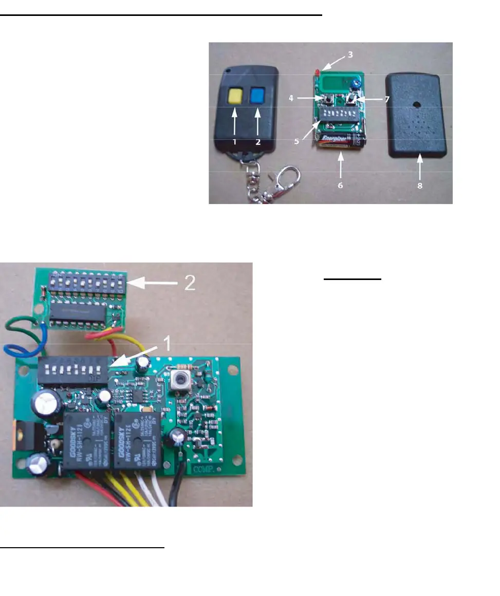
Transmitter/Remote Control (shown in Figure 9)
1. Yellow Button Channel
2. B
lue Button Channel
3. In
dicator Light
4. Yel
low Button Channel – exposed
5. DIP S
witch
6. B
attery
7. B
lue Button Channel – exposed
8. Back side cover
Figure 9
Receiver
1. Channel 1 DIP Switch (yellow
button o
n remote control
transmitter)
2. C
hannel 2 Dip Switch
(S
econdary, Multi-Code
compa
tible, blue button on
remote con
trol transmitter)
The r
ed and black wires are 24 volt
power i
nput. The two yellow are the
chan
nel 1, the two white are
chan
nel 2, and the black wire is the
antenna wir
e
Figure 10
Figure 10
Setting the Transmitter DIP Switches:
T
here are a total o
f eight (8) transmitter DIP switches. Each one can be placed in three (3) different positions
(+, 0, -).
DO NOT set all of the switches to the same position, for example: all +, all 0 or all -. Once the
DIP switches have been set to a personal code, replace and close the cover.
11