DKC400 (U) Y SLIDING GATE OPERATOR USER’S MANUAL
4
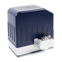
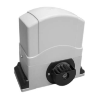
4. Working principle and main structure
The device is composed of a single-phase motor, worm and worm gear. The main shaft of the
motor rotates the worm with the clutch engaged, the worm rotates the worm gear and output
gear, which pushes the rack attached to the sliding gate, thus moving the gate.
The device is installed with a thermal protector, the thermal protector will switch off the motor
automatically in case of the temperature is higher than 120°C and switch on the motor
automatically when the temperature is lower than 85°C±5°C.
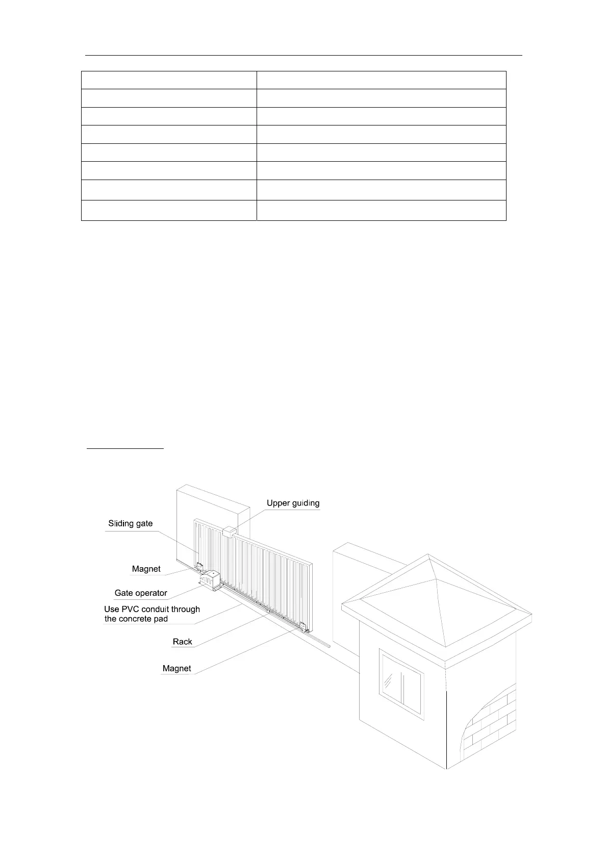
5. Installation and adjustment
The DKC400(U)Y rack-driven gate operator operates by forcing a drive rack past a drive gear.
The entire configuration is shown in Fig.1. The gate operator must be installed on the inside of
the gate.
Gate preparation
Be sure the gate is properly installed and slides smoothly before installing the DKC400(U)Y
sliding gate operator. The gate must be plumb, level, and move freely.
Fig.1
Limit switch Magnetic limit switch
Remote control operating range 30m
Frequency 433.92mHz
Remote control mode Single-button
Auto-close time 0-44 sec.
Working time 90 sec.
Noise
≤62dB
Environmental temperature
-10ºC~+55ºC