1. Check again for completed and correct assembly of your swing gate opener and gate. Plug the Power
2. Single/Dual Gate Set
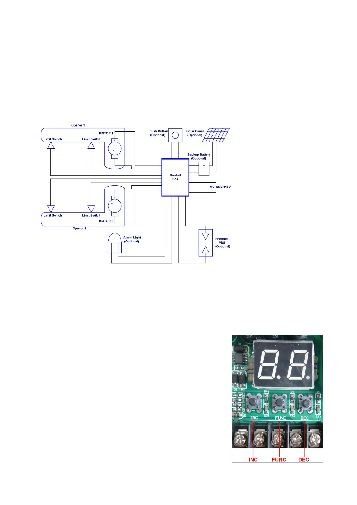
Press and hold the “FUNC” Button for more than 4 seconds.
The Digital Display will indicate “P1”. Gate opener is on the
SINGLE/DUAL Gate setting. Press the “INC” and “DEC”
Buttons respectively to following modes:
“01” shown in Digital Display, it is Single Arm 1 (right-hand
side) mode. “10” shown in Digital Display, it is Single Arm 2
(left-hand side) mode. “11” shown in Digital Display, it is Dual
arm mode.
Press the “FUNC” button to store the data when the single or
dual gate is chosen. The Digital Display will indicate “P2”. Now
single/dual gate set is finished.
(Factory set is “11”)



 To Next Page