Step 3
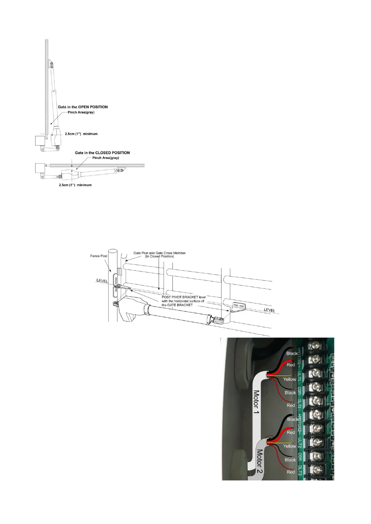
With the gate in closed positions and with the opener in their retracted positions, place the opener with
the gate bracket and post bracket assembly on to the gate post and the gate. Position the gate bracket
and the post bracket assembly so that the gate opener is level with the horizontal cross member of the
gate. While holding the opener in the desired level position, temporarily secure with two C-clamps.
Step 4 to Step 9
Repeat the Step 4-9 in P 11-13.
Step 10
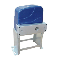
The motors’ power wires and limit wires connection by
“Push to Open” is different from the connection by “Pull
to Open”. So motor 1 and motor 2 wires should be
connected to the control box as the instruction in the right,
not according to the instructions in page 16.
Black thick wire should be inserted into the Motor+
terminal. Red thick wire should be inserted into the Motor-
terminal, the Yellow wire into ULT1 terminal and the Red
wire into DLT1 terminal. Black wire is still into COM
terminal.