22
• Set the number of cycles for Low Level Counter “” that are permitted after
low level is detected. The system will not dispense once low level is detected
when the low level counter function is disabled.
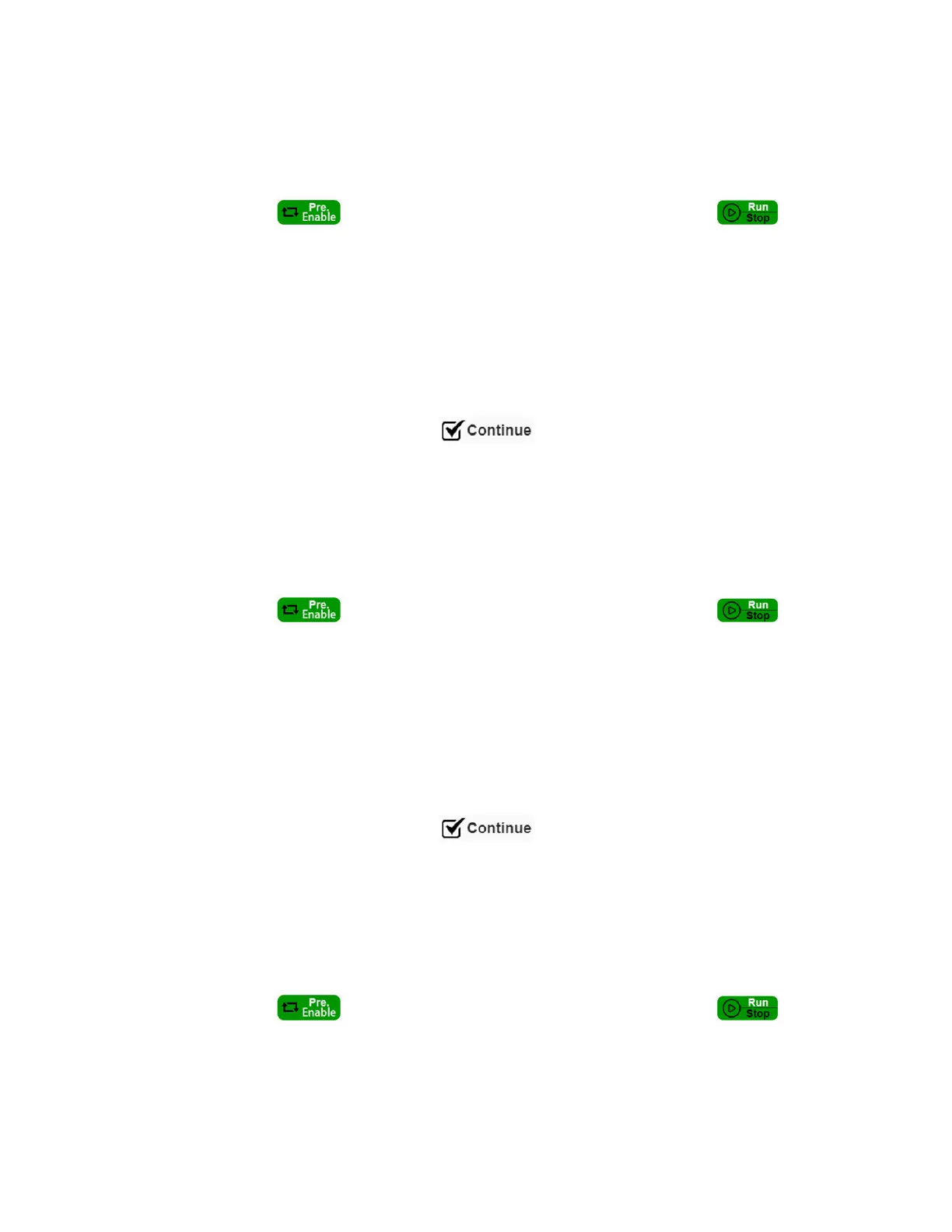
• Click “ ” button to pressurise the reservoir and select “ ” run
working mode. The system is ready for dispensing in “Time” mode.
5.6.3 Continue Mode (Single dispense valve)
• Connect electrical and pneumatic supplies and dispense valve as described in
section 4.2
• Place adhesive bottle in the reservoir as described in section 4.3
• Enter Setting page, select “ ” run mode for channel A or Channel B
• Click the “+”/”- “increase/reduce the value or enter direct numerical input to
set the reservoir pressure and acceptable range,
• Set the number of cycles for Low Level Counter that are permitted after low
level is detected. The system will not dispense once low level is detected
when the low level counter function is disabled.
• Click “ ” button to pressurise the reservoir and select “ ” run
working mode. The system is ready for dispensing in “Continue” mode.
5.6.4 Continue Mode (Two dispense valves)
• Connect electrical and pneumatic supplies and dispense valve as described in
section 4.2
• Place adhesive bottle in the reservoir as described in section 4.3
• Enter Setting page, select “ ” run mode for channel A & Channel B.
• Click the “+”/”- “increase/reduce the value or enter direct numerical input to
set the reservoir pressure and acceptable range,
• Set the number of cycles for Low Level Counter that are permitted after low
level is detected. The system will not dispense once low level is detected
when the Low Level Counter function is disabled.
• Click “ ” button to pressurise the reservoir and select “ ” run
working mode. The system is ready for dispensing in “Continue” mode.