T
Timothy SaundersAug 14, 2025
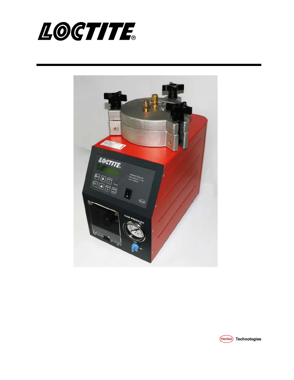
Why is my Loctite 1390321 not dispensing product correctly?
- CClaire WalkerAug 14, 2025
If your Loctite Dispenser isn't dispensing product, dispensing too little, or dispensing too much, here's what to check: * Ensure the dispensing pressure is correctly set. * Verify the air pressure hose is properly connected. * Replace the Luer-Lock tip cap with a dispensing needle. * Replace the dispensing needle if it's clogged, too small, or too large. * Check the dispensing valve. * Confirm the product reservoir is switched on and not empty. Refill if necessary.