8
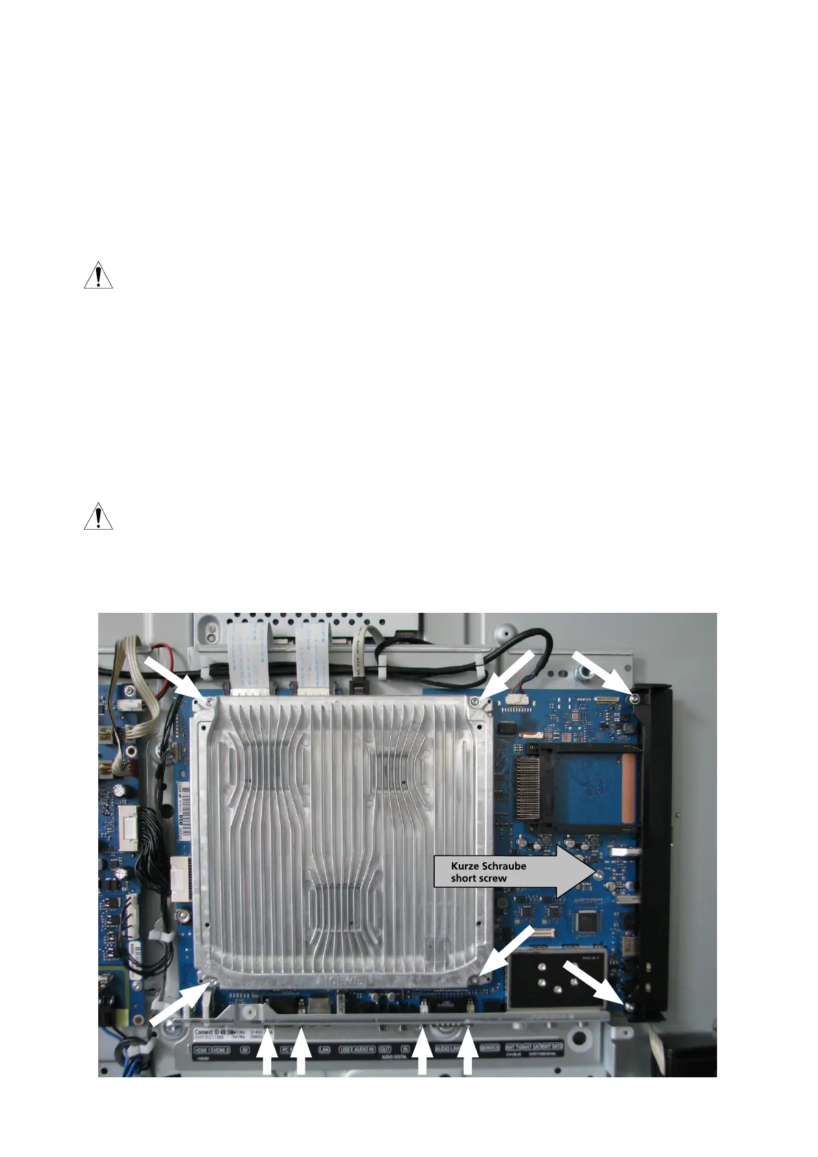
Abb. 7 / Fig. 7
3.2. Aus-/Einbau Signal-Board
Das Signal-Board ist mit sieben Torxschrauben mit der Größe T10 und vier Sechskantschrauben mit dem Chassisträ-
ger verbunden, siehe Pfeile in Abb 7.
Folgende Kabelverbindungen müssen gelöst werden:
W1013, W1025, W 1032, W1033, W1135 und W1035 (nur bei DR+ Geräten).
Die Lage der Kabelverbindungen nden Sie im angefügten Verdrahtungsplan.
Die Montage erfolgt in umgekehrter Reihenfolge.
Achtung:
Bei der Montage der Baugruppe ist darauf zu achten, dass die kurze Schraube an der Position
mit grauem Pfeil in Abb. 7 verschraubt wird.
3.2. Removal / installation of signal board
The signal board is xed to the chassis support with seven T10 Torx screws and four hexagon screws, see arrows
in g. 7.
The following cable connections must be disconnected:
W1013, W1025, W1032, W1033, W1135 and W1035 (only with DR+ devices).
The position of the cables can be found in attached wiring plan.
To assemble, follow the instructions above in reverse order.
Attention:
When assembling the component, make sure that the short screw is screwed in at the position
with the grey arrow in g. 7.