7
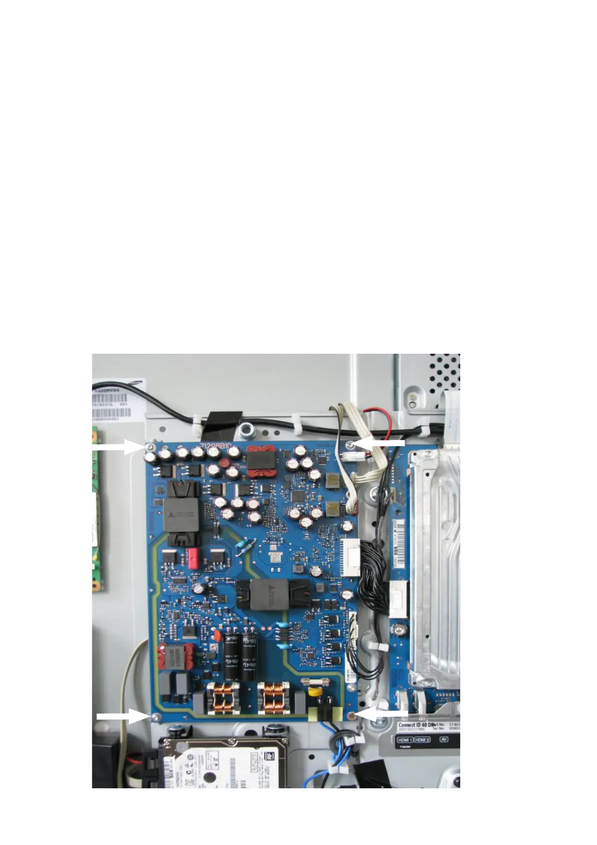
Abb. 6 / Fig. 6
3. Aus-/Einbau der Baugruppen
3.1. Aus-/Einbau Basic-Board
Entfernen Sie die Kabelverbindungen W1000, W1002, W1004, W1006, W1007 und W1009 (nur bei DR+ Geräten).
Die Lage der Kabelverbindungen nden Sie im angefügten Verdrahtungsplan.
Das Basic-Board ist mit vier Torxschrauben der Größe T10 mit dem Chassisträger befestigt, siehe Pfeile in Abb.6.
Die Montage erfolgt in umgekehrter Reihenfolge.
3. Removal / installation of components
3.1. Removal / installation of basic board
Remove the cable connections W1000, W1002, W1004, W1006, W1007 and W1009 (only with DR+ devices).
The position of the cables can be found in attached wiring plan.
The basic board is xed to the chassis support with four T10 Torx screws, see arrows in g. 6.
To assemble, follow the instructions above in reverse order.