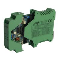
Installation Manual WTS3 Series II
M013610b.doc 5
TERMINAL BOARD CONNECTIONS
P
OWER SUPPLY
Use a power cable, with suitable protection to the environment in which they are installed, with a
maximum section of 1.5 sqmm.
L
OAD CELLS
Load cell output is a low level signal (few millivolts); then it is necessary to use a good quality
shielded cables.
A 4 or 6 wires twisted pairs 100% shielded cables is recommended. Refer to enclosed drawing to
match the cable twisted pair correctly.
C
URRENT AND VOLTAGE OUTPUTS
Shielded cables should be used also for analog output connection to external devices.
The 0-10 Vdc and 4-20 mA outputs are galvanically isolated from the power supply (+24 Vdc and
negative Com24).
The negative output voltage (-Vout) is connected internally to the negative output current (-Iout).
Voltage and current outputs can be used at the same time to connect two different devices.
The current output is active and provides for a maximum load (impedance of the connected load)
of 500 ohms. This means that can also operate with an impedance of zero since the output is
virtually a current generator.
The output voltage is low power (voltage). Is allowed a maximum load of 2 mA (load impedance
equal to 5 Kohm) purely resistive.
The standard calibration range is from 0 to 10 V which corresponds to the 4-20 mA range
(calibration standard factory).
It is possible select the range 0-20 mA. In this case you must repeat the calibration procedure as
described later.

 Loading...