Installation Manual WTS3 Series II
M013610b.doc 8
CALIBRATION PROCEDURE
If not otherwise specified, the device will come with the following setting range :
• Input : 0 - 2 mV/V
• Voltage output : 0 - 10 Vdc
• Current output : 4 - 20 mA
If you need a different range of calibration steps below.
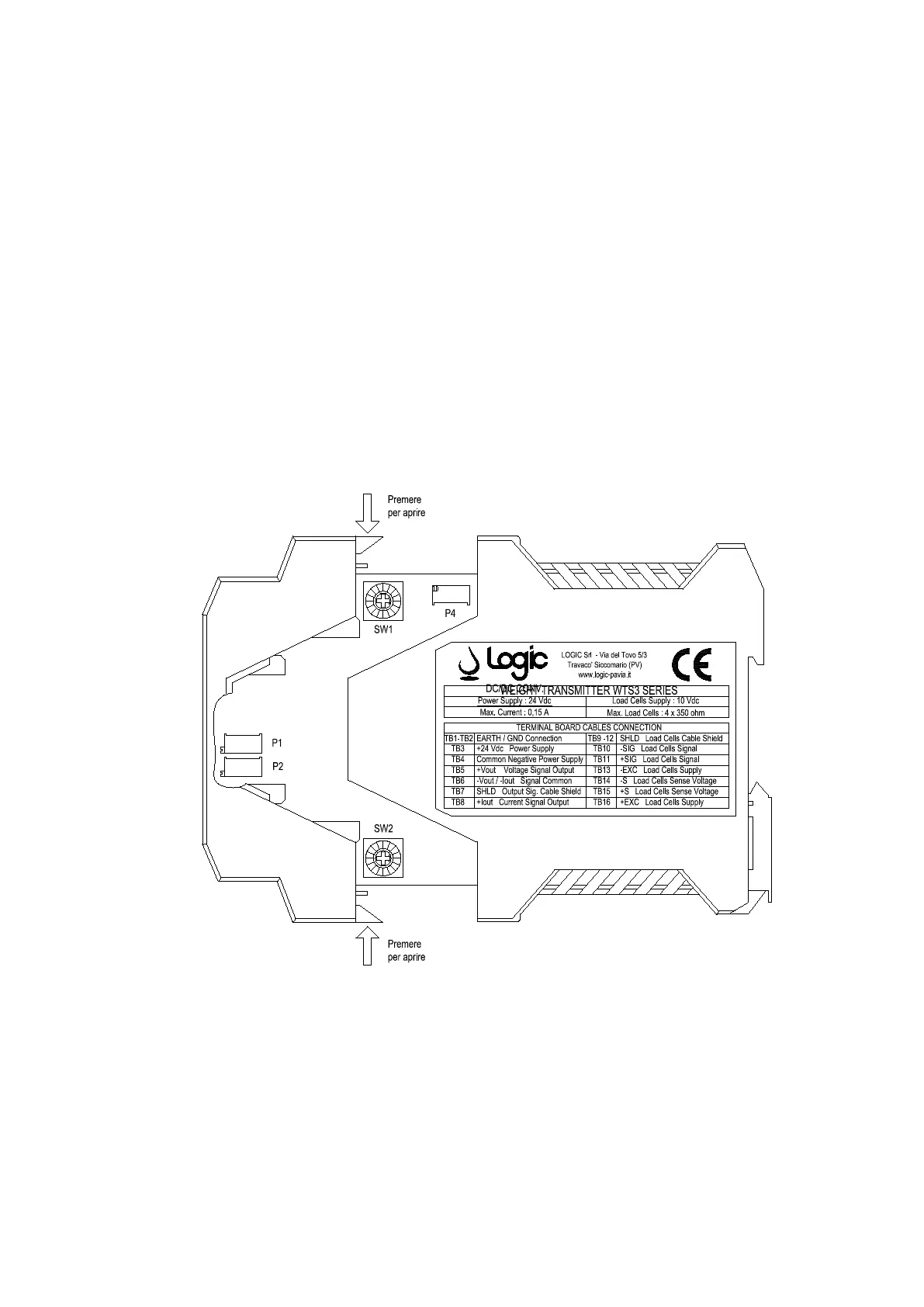
After you have made and checked the connections steps follows :
• Open the plastic case by pressing on the locking tabs located near the terminals 2-3 and
14-15 as shown in Fig.
• Pull the board up to make accessible the trim-pots and switches to be operated, keeping
the attached cables (the cables connected to the terminals will be mobile enough).
 Loading...