4.4 Making RS485 communication cable and connecting
Recommended RS485 communication cable is 0.5mm
2
twisted-pair with 10mm stripping length.
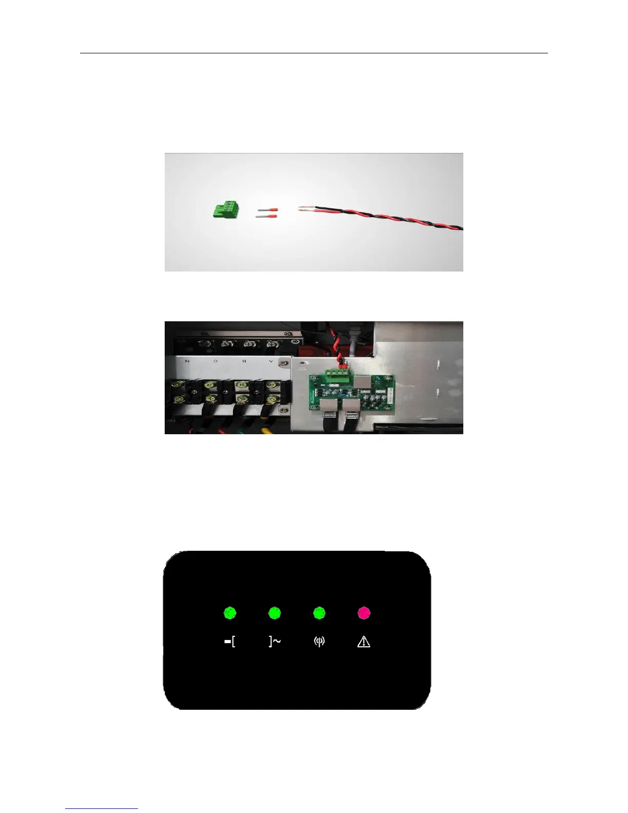
Step 1: Use a wire stripper to strip the insulation layer of RS485 cable at a suitable length.
Step 2: Connect the red tube terminal to the RS485 cable, and press it firmly with a crimping plier.
Step 3: Insert the pressed RS485 cable into the corresponding RS485 waterproof terminal and follow below picture to
connect the cable. (RS485-A on the PCB corresponds to red; RS485-B on the PCB corresponds to black)
5 LED Indicator Lights
5.1 LED status information
There are 4 LED indicator lights on the inverter LED panel to display the system state or alarm.