Step 4: Insert terminals with connected wires into corresponding + and – terminal at the bottom of inverter.
.
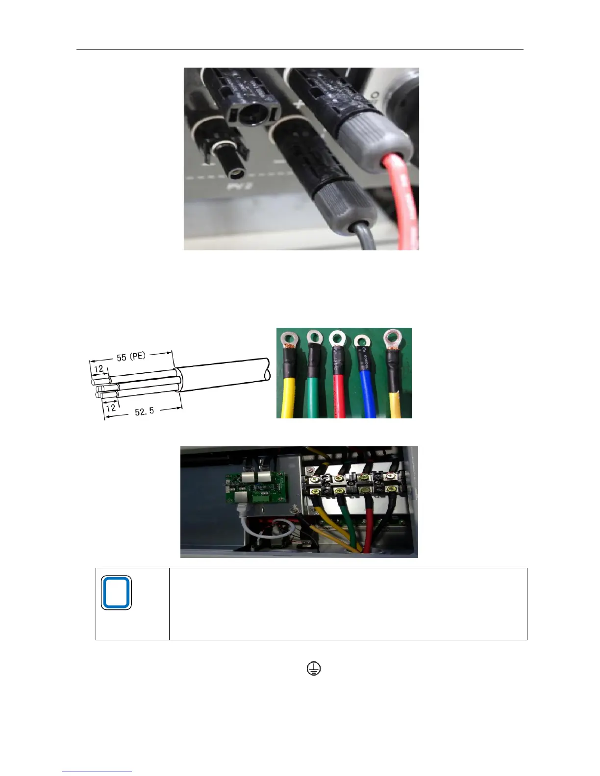
4.3 Making the inverter output cable and installation instructions
Step 1: Use wire stripper to strip the sheath and insulation layer from AC output cable at a suitable length, and press the
terminal firmly.
Step 2: Put the AC output cables (L1, L2, L3, N, PE) into the waterproof terminals.
Making the inverter output cable and installation instructions is only for reference. Please
note that EA30-33KTLSI output wiring is 3W + N + PE; EA35-40KTLSI output wiring is 3W
+ PE.
For specific internal installation wiring, refer to the output specification value of the inverter
grid.
Step 3: Use a Phillips screwdriver to loosen the bolt in each jack, and insert each cable into the corresponding position,
and then tighten each bolt. PE cable is connected to jack.
Step 4: Tighten the sealing cap to the housing.