Description of LED main interface
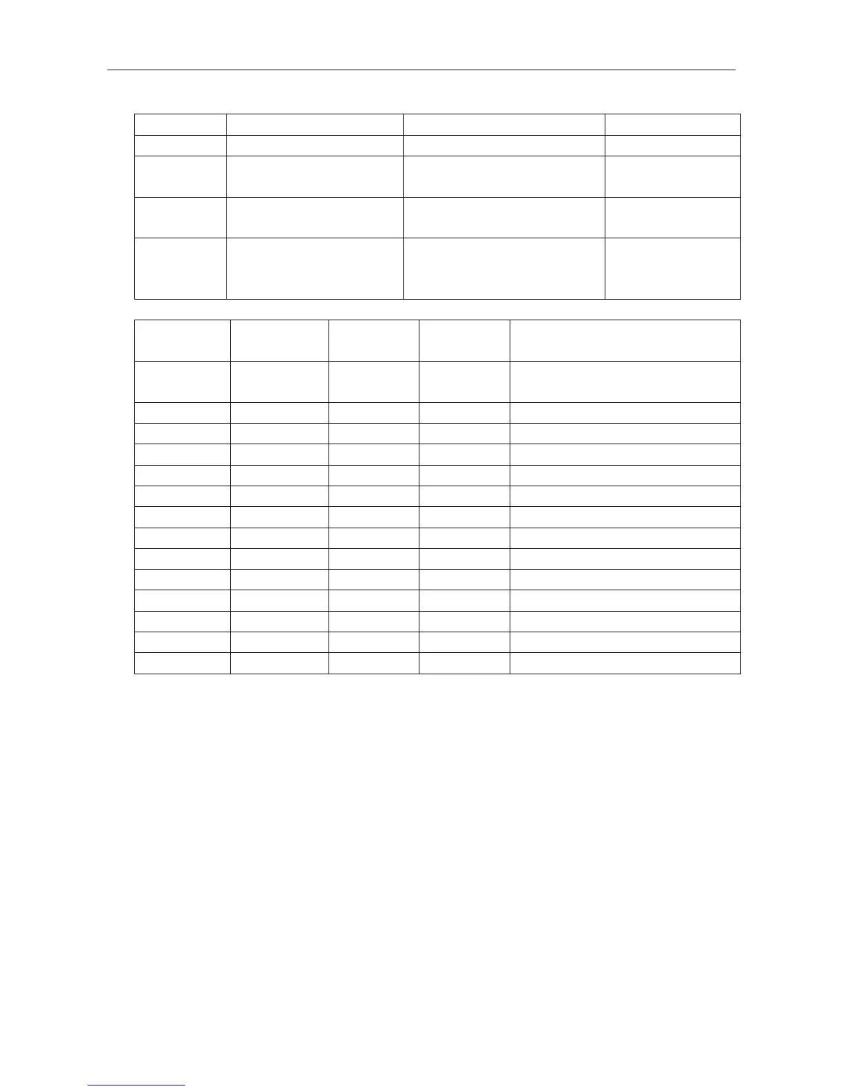
When work normally, LED indicator lights indicates:
PV input voltage is less than 200 V
The inverter is connected to the
grid
The inverter is not connected to the
grid
RS485 communication interruption
RS485 communication
normal
When the inverter is in the state
of self-test, standby, sleep and
shutdown
The system is in the grid-connected
state, and no fault alarm
When the system has
fault alarm
When insert U disk, carry out USB-related operations:
Flashes 5 times, U disk is inserted or
pulled out
Loading firmware upgrade file
DSP1 is in the process of upgrade
DSP2 is in the process of upgrade
CPLD is in the process of upgrade
● LED indicator is illuminated ○ LED indicator is not illuminated ☆LED indicator flashes
5.2 View alarm information
User can follow the tips of LED indicator lights to view the inverter fault information.
Export history with U disk.
Connect monitoring and control software via RS485/NET communication to view running information of the
equipment.
Connect APP via Wi-Fi / GPRS (optional) communication devices to view running information of the system.