Do you have a question about the Lombardini 12LD 435-2 and is the answer not in the manual?
Provides essential guidelines and best practices for using the service manual effectively and safely.
Details the terms and conditions of the warranty provided by Lombardini for its engines.
Defines key terms and acronyms used throughout the workshop manual for clarity.
Explains the meaning of various symbols and decals used to indicate safety precautions and hazards.
Outlines crucial safety rules and operational procedures to prevent accidents and ensure safe engine use.
Guides users through identifying and resolving common engine operational problems and anomalies.
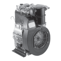
Details how to identify engine model, serial number, and other vital manufacturer-specific information.
Presents detailed technical data, dimensions, and performance parameters for various engine models.
Illustrates engine performance curves (power, torque, fuel consumption) under different operating conditions.
Provides detailed dimensional drawings and measurements of the engines for installation and space planning.
Details the regular checks and operations required for maintaining the engine's performance and longevity.
Outlines less frequent, but critical, maintenance tasks that go beyond routine service.
Provides guidance on selecting the correct type of lubricating oil based on viscosity and international specifications.
Explains the SAE grading system for engine oils based on viscosity at different temperatures.
Covers API, MIL, and ACEA standards for engine oil qualification and performance.
Details ACEA sequences for petrol and diesel engines, classifying oil performance standards.
Lists API and MIL sequences for engine oils, categorizing them by diesel and petrol applications.
Specifies the recommended lubricant brand, specifications, and oil capacities for 12 LD engines.
Defines the required characteristics of diesel fuel for optimal engine performance and longevity.
Provides guidance on using special winter fuels to prevent issues in cold weather conditions.
Provides essential safety and procedural guidelines for engine disassembly and reassembly operations.
Offers crucial advice for performing engine overhauls and tuning procedures correctly and safely.
Details the procedures for checking, cleaning, and replacing the dry air cleaner element.
Explains the process for removing and refitting the engine flywheel, including torque specifications.
Covers the removal and refitting of the alternator, including tightening torques for its components.
Details the procedure for checking and adjusting valve and rocker arm clearance when the engine is cold.
Describes the procedure for checking and setting the optional compression release mechanism.
Covers the inspection, dimensions, and refitting of the rocker arm assembly, including lubrication checks.
Explains how to check and adjust the injector nozzle projection using copper shims.
Provides instructions for removing and refitting the cylinder head, emphasizing precautions against deformation.
Details the removal, replacement, and fitting of valves, springs, and seals.
Covers checking dimensions and fitting procedures for valve guides and their housings.
Explains the process of inserting valve guides into the cylinder head, including heating procedures.
Describes the process of pressing valve seats into housings and cutting the seat angle.
Details the procedure for grinding valve seats using fine emery paste and checking sealing surface.
Explains how to measure cylinder diameter and identify wear for piston and ring replacement.
Outlines how to check cylinder surface roughness and integrity using air and water immersion.
Details the process of removing pistons, cleaning grooves, and measuring piston diameter for wear.
Explains the importance of weighing pistons for balance and the acceptable weight difference.
Describes how to measure the end gap of piston rings to ensure proper fit within the cylinder.
Details how to check the clearance between piston rings and their respective grooves.
Provides the correct order and orientation for installing piston rings onto the piston.
Explains the correct method for refitting pistons into the cylinder, including lubrication and circlip checks.
Details how to measure and adjust piston clearance using head gaskets for correct engine operation.
Provides dimensions and clearance specifications for the connecting rod small end bushing.
Covers the refitting of connecting rod big end bearings, including notch alignment and torque.
Explains the procedure for weighing connecting rods to ensure balance and the acceptable weight difference.
Details the use of special tools for removing the crankshaft timing gear.
Describes the removal of the main bearing support on the timing gear side, including screw usage.
Details the removal of the main bearing support on the PTO side, including oil seal checks and tightening nuts.
Explains how to straighten and unscrew the locating bolt before removing the crankshaft.
Details how to check crankshaft end play using a feeler gauge and setting it with gaskets.
Covers refitting the center main bearing support, emphasizing notch alignment and screw tightening.
Describes how to clean crankshaft lubrication ducts using a pointed tool and compressed air.
Provides the required radius value for connecting journals to shoulders on the crankshaft.
Lists internal diameter dimensions for main bearings and connecting rod big end bearings.
Provides clearance values between crankshaft journals/pins and connecting rod bearings.
Lists the reference dimensions for the main bearing supports (PTO-side, Central, Timing gear side).
Provides the reference dimensions for the main bearing housings.
Lists dimensions and clearances for camshaft journals and their housings.
Details the procedure for measuring intake and exhaust cam height for proper valve timing.
Explains how to align camshaft and crankshaft timing gears using timing marks and tightening torque.
Describes how to check camshaft end play using a dial gauge and the acceptable range.
Provides a method for setting valve timing without relying on timing marks, using tappet height.
Details the components and maximum torque for the hydraulic pump PTO.
Explains the working principle of the mechanical speed governor and its components.
Describes the components and assembly of governor springs with the rocker arm.
Details the function and components of the spring providing extra fuel for starting.
Overview of the engine's lubrication and breather recirculation system, including safety warnings.
Details how to check the oil pump for gear integrity, clearance, and oil pump delivery.
Describes the components, features, and specifications of the internal oil filter cartridge.
Details the components, characteristics, and specifications of the external oil filter cartridge.
Explains the details and operating pressure of the oil pressure relief valve for engines with internal oil filters.
Presents the oil pressure curve at idling speed based on temperature and engine speed.
Presents the oil pressure curve at full engine speed based on temperature and engine power.
Illustrates the components and layout of the fuel feeding and injection system.
Details the components and assembly of the fuel filter located inside the fuel tank.
Describes the characteristics and maintenance of the fuel filter removed from the tank.
Explains the operation, components, and characteristics of the fuel feeding pump.
Lists and illustrates the components of the injection pump.
Provides test data for injection pump delivery, including rod stroke, RPM, and plunger difference.
Guides users through the process of reassembling injection pump components after replacement.
Details the procedure for synchronizing the injection pump and mechanical speed governor timing.
Explains how to adjust the injection static advance using a valve lowering tool and dial indicator.
Details the components of the injector for standard engine models.
Details the components of the injector for EPA engine models.
Describes how to connect injectors to a hand pump, check setting pressure, and make adjustments.
Illustrates the electrical starting system, including the alternator, starter motor, and battery charging light.
Provides dimensions and notes for the 12.5 V, 14 A alternator.
Presents the battery charging curve for the 12.5 V, 14 A alternator.
Covers optional electrical components like alternators and voltage regulators.
Provides dimensions and notes for the 12 V, 18 A alternator.
Presents the battery charging curve for the 12 V, 18 A alternator.
Details voltage regulator types, connections, and sizing for SAPRISA and DUCATI systems.
Guides on how to properly check the operation of the voltage regulator using a voltmeter and ammeter.
Provides specifications and important notes for the Bosch DWL 12 V, 1.7 kW starter motor.
Illustrates characteristic curves for the Bosch DWL starter motor, showing voltage, power, torque, and current.
Details how to adjust the engine's idling speed in no-load conditions after warm-up.
Explains how to set the engine's full speed in no-load conditions using the adjustment screw.
Describes the procedure for setting the injection pump delivery, ideally on a torque dynamometer.
Explains the function of the delivery limiting device and its role in torque setting and extra fuel supply.
Provides detailed steps for setting injection pump delivery using a torque dynamometer and checking fuel consumption.
Details the procedure for setting the engine's stop mechanism, including lever and retainer adjustments.
Outlines the necessary steps for protecting engines when they are not used for extended periods.
Details the steps for protecting the engine's internal components during storage, including oil changes.
Explains how to protect the fuel injection system during engine storage, involving fuel tank and filter procedures.
Covers measures for protecting the engine's external surfaces and components from environmental factors during storage.
Lists essential steps to perform before restarting an engine that has been in storage.
Provides a table of tightening torques for various main engine components, listed by position.
Lists specific positions where Loctite sealants should be applied and the types of sealant to use.
Details tightening torques for standard screws with coarse threads, categorized by diameter and resistance class.
Details tightening torques for standard screws with fine threads, categorized by diameter and resistance class.
Lists specialized tools and their part numbers required for engine maintenance and repair procedures.
| Number of Cylinders | 2 |
|---|---|
| Cooling System | Air-cooled |
| Fuel System | Direct injection |
| Lubrication System | Forced lubrication with gear pump |
| Governor Type | Mechanical |
| Engine Type | Diesel |
| Starting System | Electric start |
| Oil Capacity | 2.5 liters |