12
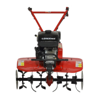
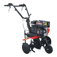
Chapter IV Operation method of the mini tiller
i. Assembly after unpacking
1. Installation of wheel: install the wheels onto both ends of output shaft and use 2 locking pin assemblies
to secure them.
2. Installation of drag bar: fix the drag bar connector onto the hitch box, use a hitch pin to connect them,
and insert a Φ 3.5× Φ 13×81 clip; then insert the drag bar into the square hole of the connector and use a Φ
8×43 pin and a Φ2.5×Φ9×46 clip to secure them.
3. Installation of handlebar assembly: align the tooth disc on the handlebar to the tooth disc on the
handlebar seat, take care to adjust the vertical position of the handlebar, and use the adjusting handle and a M16
×140 bolt to connect handlebar assembly onto the handlebar seat and tighten it.
4. Installation of shift lever: insert the shift lever through the hole of the handlebar seat’s lug, and into the
hole of the gear shift arm, and then use a Φ2.5×Φ9×46 clip to secure it. Put the shift lever in the neutral
position.
5. Refer to the illustrations of the mini tiller’s accessories for information about assembling of the mini
tiller.
ii. Installation and adjustment of cables
1.Adjustment of clutch cable (see Figure 2 and Figure 4).
 Loading...