EN
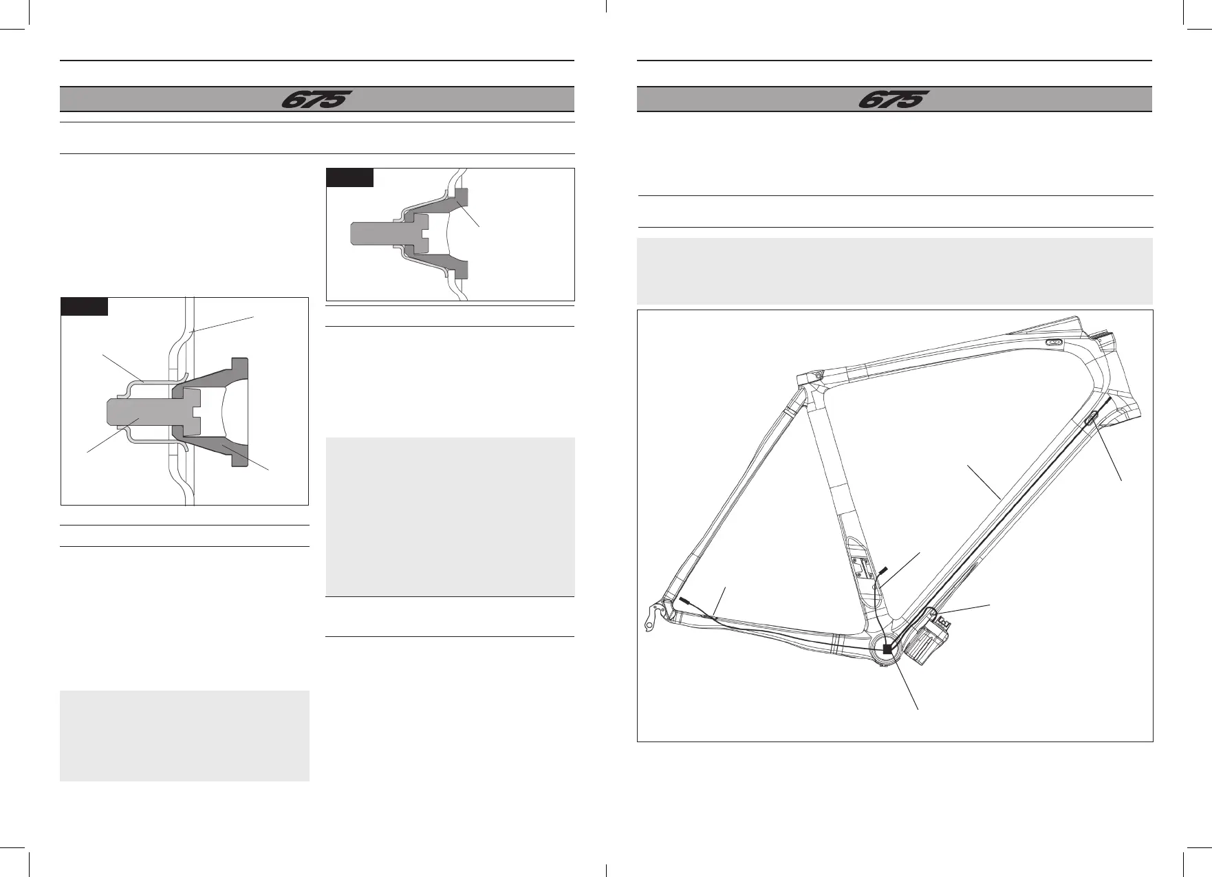
ASSEMBLY OF SHIMANO DI2 & CAMPAGNOLO EPS ROUTING
For more information about the installation of the DI2 or EPS routing systems, please see the
manufacturer’s instructions. (Example of assembly with the battery under the diagonal tube. Other
assemblies are possible: read the construction instructions.)
DI2 / EPS
cable stop
DI2 / EPS
cable stop
DI2 / EPS
drill hole
DI2 / EPS drill hole, assembly
of the recommended battery
under the crank
Optional DI2 / EPS drill hole for
assembly of the battery on the
diagonal tube
Main connector (insert
perforated housing)
Thanks to its cable stops, your 675 frame can be mounted with a mechanical or electrical unit (DI2 or
EPS).
EN
24 25
REMOVABLE CABLE STOPS
DISMANTLING
Cable stop in posi-
tion in its housing
1. Ensure that the cable stop is in the open
position.
2. Position the cable stop in its housing,
against the composite wall of the frame (Fig. f).
3. Lightly tighten the adjusting screw (1 Nm)
until the housing retainer is in its housing (Fig.
g).
The rear brake wire runs without housing inside
the horizontal tube.
1. Remove the cable stop for the rear break
(located at the end of the horizontal tube).
2. Place the rear break housing in the housing
located at the beginning of the horizontal tube.
3. Run the brake wire so that it exits via the
housing of the break located at the end of the
horizontal tube.
4. Re-fit the housing located at the end of the
horizontal tube.
Remove the housing possibly lodged in the cable
stop.
1. Undo the adjusting screw until the cable stop
and the housing come free of each other.
2. Extract the cable stop. If the stop resists
extraction, undo the adjusting screw further.
The 675 is equipped with removable cable
stops that can be used for the assembly of
electrical units.
Originally, the cable stops were intended for
fitting a mechanical unit.
For an electrical unit one must use the specific
cable stops supplied with the frame.
Important: Excessive tightening of the
adjusting screw may damage the screw
threads or the retaining spring. The cable
stops’ stability may be impacted.
Important: The end piece of the
adjusting screw is flattened so as to
avoid disengagement of the retaining
spring when loosening. Do not force the
loosening or the retaining spring may
disengage and damage its threads or
those of the adjusting screw. It may also
impact the positioning of the end cap or its
disengagement.
Retaining spring
Frame
Adjusting screw
Cable stop
Fig. f
Fig. g
 Loading...