LLR60132/60134_080604 Page 9 of 33
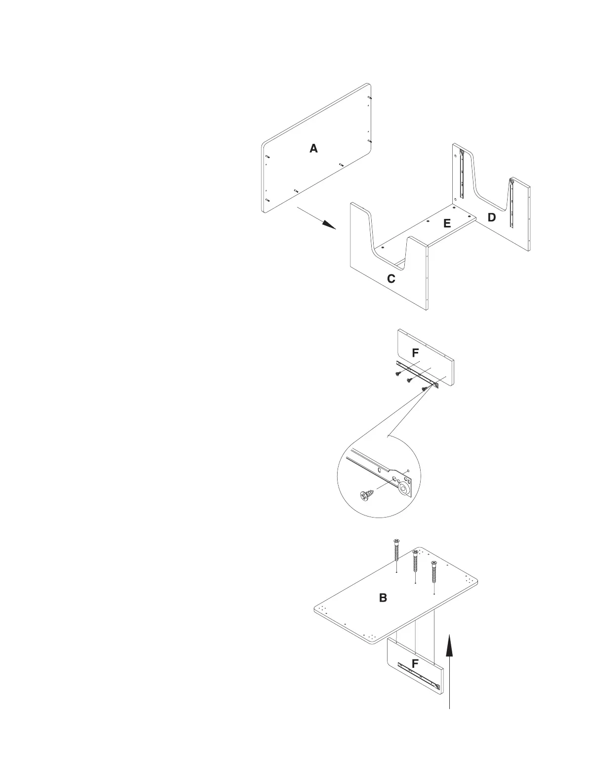
Step 7
Attach the Table Panel (A) to the
Left Side Panel (C), Right Side
Panel (D) and Back Panel (E).
Ensure that the Cam Locks (2)
properly engage with the Cam
Screws (1). With a Phillips Screw
Driver, rotate the cam locks 1/2 turn
clockwise until snug. DO NOT
OVERTIGHTEN
Step 8
With the Middle Side Panel (F)
laying on a non-abrasive surface
install the right side Case Slide (9)
as shown on the drawing with 3
each 4X14 Screw (8). NOTE: See
drawing for proper placement of
the case slide.
Step 9
Using a Phillips Screw Driver and 3
each Long Screw (5) attach the
Middle Side Panel (F) to the Bottom
Panel (B) as shown on the drawing.
Left side panel
Table panel
Right side panel
Back panel
Middle side panel
Bottom panel
Middle side panel
 Loading...