LLR60132/60134_080604 Page 8 of 33
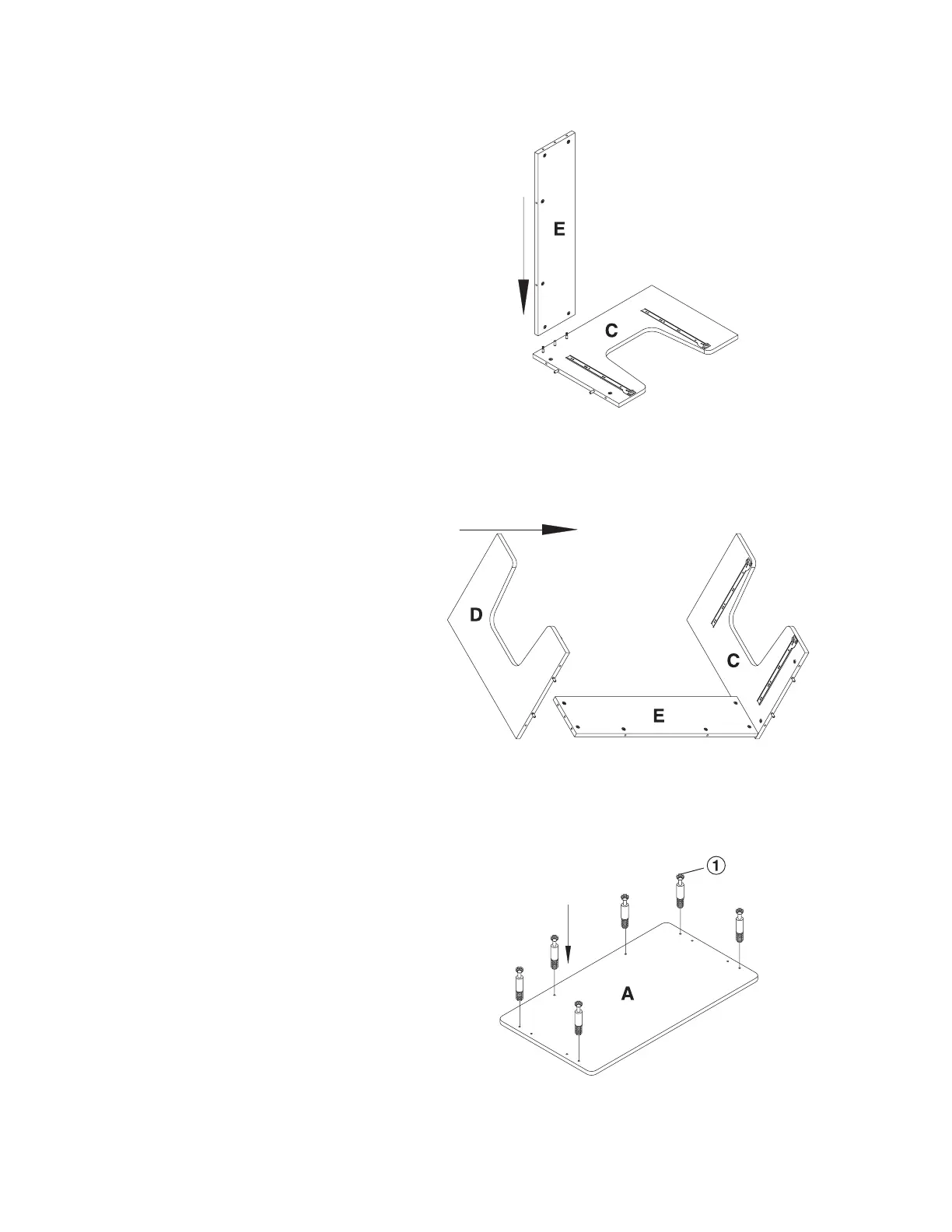
Step 4
Attach the Back Panel (E) to the
Left Side Panel (C) ensuring that the
Cam Lock (2) properly engage with
the Cam Screw (1). With a Phillips
Screw Driver, rotate the cam locks
1/2 turn clockwise until snug. DO
NOT OVERTIGHTEN
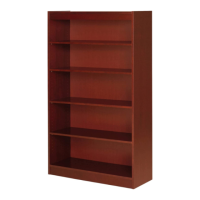
Step 5
In the same fashion, attach the Right
Side Panel (D) to the Back Panel
(E). With a Phillips Screw Driver,
rotate the cam locks 1/2 turn
clockwise until snug. DO NOT
OVERTIGHTEN
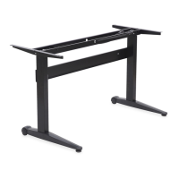
Step 6
Insert 6 each Cam Screw (1) into
the Table Panel (A) with a Phillips
Screw Driver.
Back panel
Left side panel
Right side panel
Back panel
Left side panel
Table panel