LLR60132/60134_080604 Page 7 of 33
Step 2
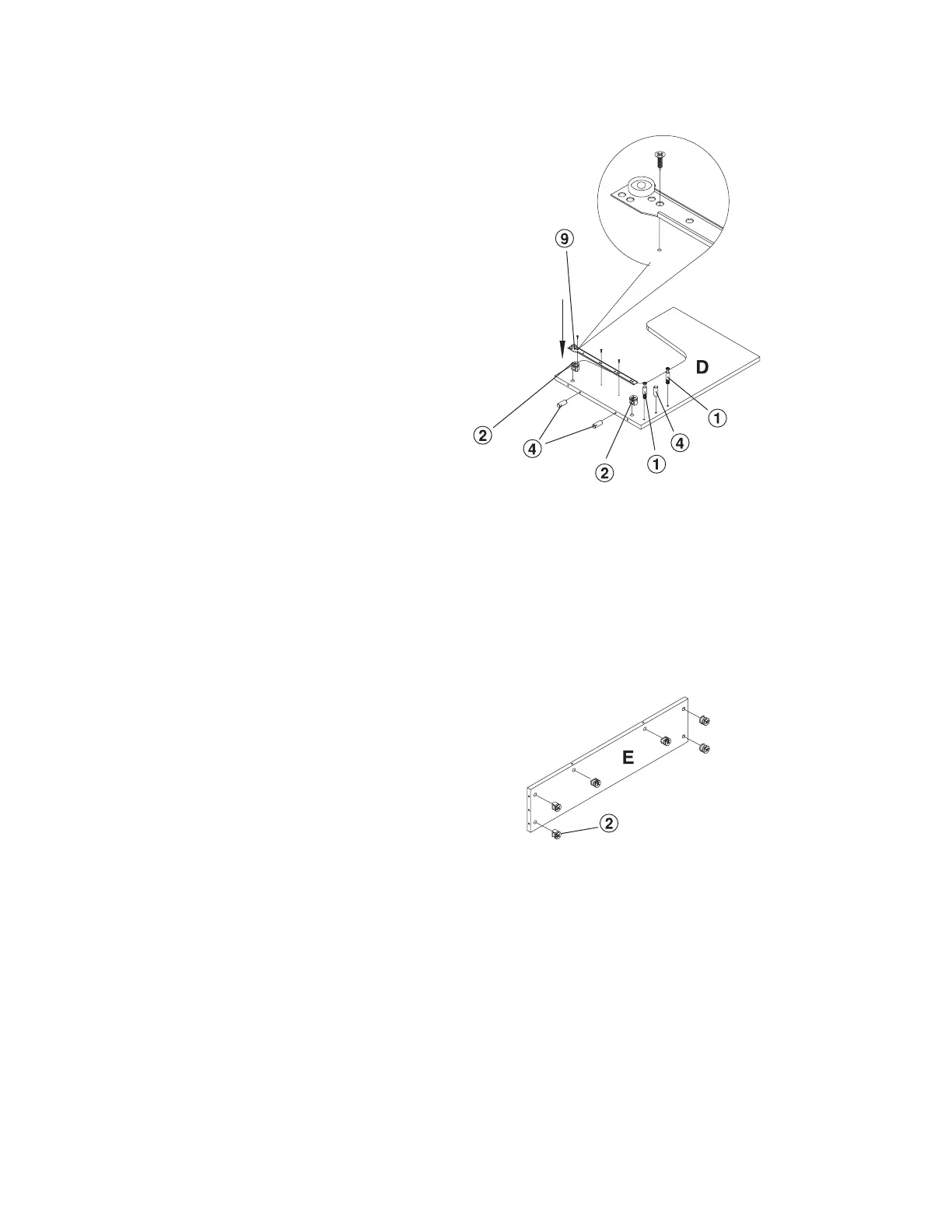
Lay the Right Side Panel (D) on a
non-abrasive surface.
Install with 3 each 4X14 Screw (8)
the 1 each right side Case Slide (9).
Please note on the drawing the
proper placement of the case slides.
With a Rubber Mallet, insert 3 each
Wooden Dowel (4) into the position
shown on the drawing.
With a Phillips Screw Driver, insert
2 each Cam Screw (1) in the
position shown on the drawing.
Insert 2 each Cam Lock (2) in the
position shown on the drawing.
When inserting the cam lock, ensure
that the arrow is facing toward the
cam screw entry.
Step 3
Insert 6 each Cam Lock (2) in the
position shown on the Back Panel
(E). When inserting the cam lock,
ensure that the arrow is facing
toward the cam screw entry.