LLR44308/44309_081104
Page 11 of 63
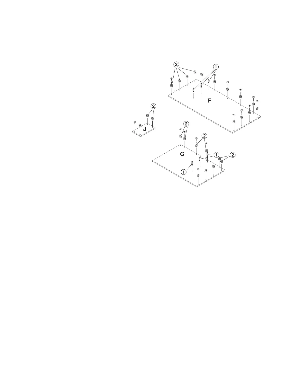
Step 3
With the 2 each Fixed Shelf on a
non-abrasive surface insert 4 each
Cam Lock (2) into each panel.
When inserting the cam lock, ensure
that the arrow is facing toward the
cam screw entry.
With the Large Back Panel (F)
laying on a non-abrasive surface
insert 13 each Cam Lock (2). When
inserting the cam lock ensure that
the arrow is facing toward the cam
screw entry.
Insert 3 each Cam Screw (1) onto
the Large Back Panel (F) in the
position shown on the drawing.
With the Return Back Panel (G)
laying on a non-abrasive surface,
insert 9 each Cam Lock (2) in the
position shown on the drawing.
When inserting the cam lock ensure
that the arrow is facing toward the
cam screw entry.
On the Return Back Panel (G) insert
3 each Cam Screw (1) in the
position shown on the drawing.
Large back panel
Fixed
shelf
Return back panel