LLR44308/44309_081104
Page 14 of 63
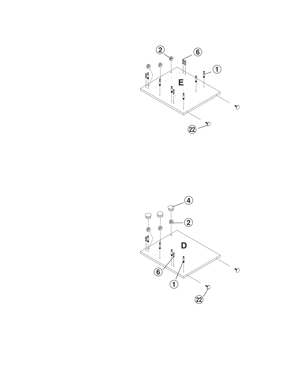
Step 8
With the Return Side Panel (E)
laying on a non-abrasive surface,
insert with a Rubber Mallet 4 each
Wood Dowel (6) in the position
shown on the drawing.
With a Phillips Screw Driver insert
6 each Cam Screw (1) in the
position shown on the drawing.
Insert 3 each Cam Lock (2) in the
position shown on the drawing.
When inserting the cam lock ensure
that the arrow is facing toward the
cam screw entry.
Screw 2 each Adjustable Foot (22)
into the bottom of the panel as
shown on the drawing.
Step 9
With the Right Side Panel (D)
laying on a non-abrasive surface
insert 2 each Wood Dowel (6) with
a Rubber Mallet in the position
shown on the drawing.
On the Right Side Panel (D) insert 4
each Cam Screw (1) in the position
shown on the drawing.
On the Right Side Panel (D) insert 3
each Cam Lock (2) in the position
shown on the drawing. When
inserting the cam lock ensure that
the arrow is facing toward the cam
screw entry.
Screw 2 each Adjustable Foot (22)
into the bottom of the panel as
shown on the drawing.
Return side panel
Right side panel