LLR44308/44309_081104
Page 18 of 63
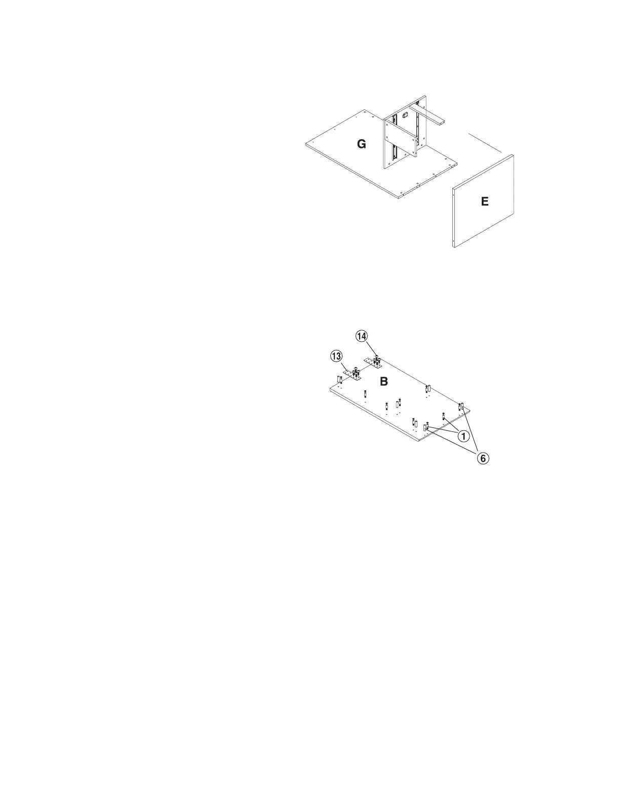
Step 14
Attach the Return Side Panel (E) to
the Return Back Panel (G), Fixed
Shelf (J) and Support Panel (K)
ensuring that the Cam Screws (1)
properly engage with the Cam
Locks (2). With a Phillips Screw
Driver rotate the cam locks 1/2 turn
clockwise until snug. DO NOT
OVERTIGHTEN
Step 15
With the Return Top Panel (B)
laying on a non-abrasive surface,
insert with a Rubber Mallet 6 each
Wood Dowel (6) in the position
shown on the drawing.
With a Phillips Screw Driver, inert 9
each Cam Screw (1) in the position
shown on the drawing.
Install the two Flat Bracket (13) to
the Return Top Panel (B) with 8
each 6X15 Screw (15).
Return back panel
Return side panel
Return top panel