LLR44308/44309_081104
Page 19 of 63
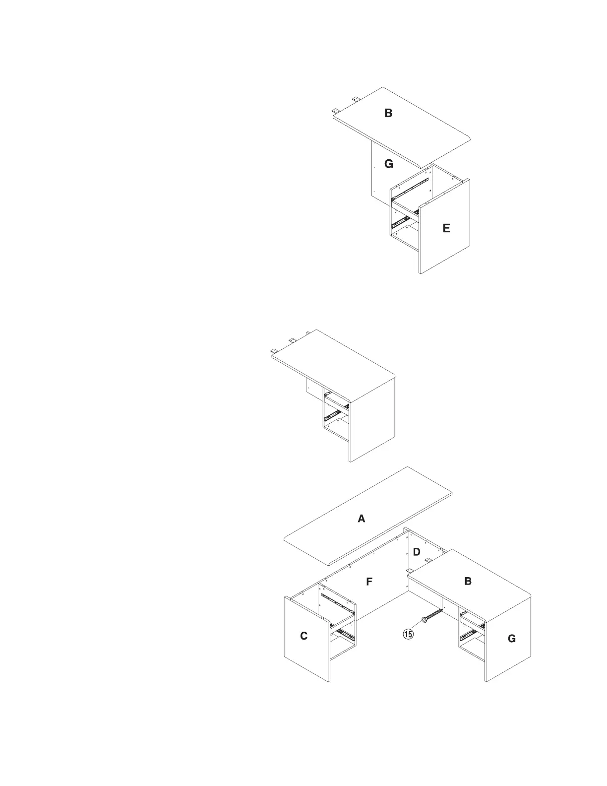
Step 16
Attach the Return Top Panel (B) to
the Return Side Panel (E), Return
Back Panel (G) ensuring that the
Cam Screws (1) properly engage
with Cam Screws (2). With a
Phillips Screw Driver rotate the cam
locks 1/2 turn clockwise until snug.
DO NOT OVERTIGHTEN.
Step 17
Attach the Large Top Panel (A) to
the partially assembled shell
comprised of the Left Side Panel
(C), Large Back Panel (F) and Right
Side Panel (D). Ensure that the Cam
Screws (1) properly engage with the
Cam Lock (2). With a Phillips
Screw Driver rotate the cam locks
1/2 turn clockwise until snug. DO
NOT OVERTIGHTEN.
Move unit into approximate position
where it will be sitting.
Attach the Return Unit to the Desk
Shell ensuring that the Flat Bracket
(13) screw holes are properly lined
up. Secure into place with 8 each
6X15 Screw (14).
With a Phillips Screw Driver, attach
3 each 4X35 Screw (15) in the
Return Back Panel (G) as shown on
the drawing.
Return back panel
Return top panel
Return side panel
Large top panel
Right side panel
Large
back panel
Left side panel
Return back panel
Return
top
panel